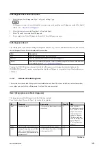
Self-diagnosis Execution Procedure
1.
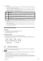
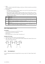
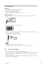
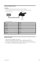
Select the type of self-diagnosis (Type 1 or Type 2) in Diag Type.
Note
Self-diagnostic items to be executed and the execution time vary depending on self-diagnosis method. For details,
refer to
“3-3-3. Details of Self-Diagnosis”
2.
Select the item to be executed from Item1 to Item7 and Item9.
3.
Select “Execute” to execute the self-diagnosis.
4.
Upon completion of the self-diagnosis, the result of the self-diagnosis appears.
Self-diagnosis Result
The self-diagnosis result consists of Diag ID (diagnostic item ID), Try, Success, and Result for the item. The result of
the self-diagnosis for each item is displayed after execution.
Item
Description
Try
Shows the number of trials of the self-diagnosis.
Success
Shows the number of internal successes of the self-diagnosis.
Result
Shows the result of the self-diagnosis. A value of 0 indicates no problem. When a value other than
0 is displayed, check the
“3-3-3. Details of Self-Diagnosis”
Pressing the CANCEL button or the jog dial with the self-diagnosis result displayed returns the display to the
INFORMATION menu. To resume normal operation after the self-diagnosis is completed, turn off and on the power
of the unit.
3-3-3.
Details of Self-Diagnosis
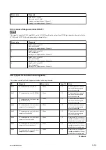
This section describes details of diagnostic items included in each Item. The values in the Error value column show
error values as a result of the self-diagnosis. A value of 0 shows normal end.
Item1 (Image processor block diagnosis)
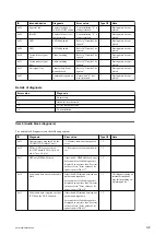
The image processor block diagnosis tests the following contents.
Type 1 takes about 10 seconds, Type 2 takes about three minutes.
ID
Diagnosis
Error value
Type1/2
Note
0x07
Lens driving check
-1: Error in iris, focus, zoom, or cor-
rection lens
2
SERVO/MANU
switch of zoom must be
set to “SERVO”. Each
ring of zoom and iris
automatically turns
during the diagnosis.
Therefore, make sure
not to touch rings dur-
ing the diagnosis.
(The focus ring does
not turn.)
0x08
Number of RPN registrations check
-1: Exceeding RPN max number
1 ,2
—
0x09
Reading/Writing data test to CMOS
block, video signal bus connection
test between CMOS and camera sig-
nal processor IC
-1: CMOS Read/Write NG or CMOS
video signal bus NG
1 ,2
—
Continued
PMW-200/PMW-EX280
3-6
Summary of Contents for PMW-200
Page 1: ...SOLID STATE MEMORY CAMCORDER PMW 200 PMW EX280 SERVICE MANUAL 1st Edition Revised 1 ...
Page 4: ......
Page 8: ......
Page 10: ......
Page 30: ......
Page 38: ...3 Install the removed parts by reversing steps of removal PMW 200 PMW EX280 2 8 ...
Page 82: ......
Page 96: ......
Page 128: ......
Page 130: ......
Page 132: ......
Page 133: ......

