1-3.
Circuit Description
1-3-1.
CMOS Block and Lens Block
BI-292/294 Boards
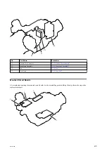
The BI-292/294 boards are used to supply power bias/synchronization signals to the CMOS image sensor (ICl) and to
transmit output signals to the VPR-124 board. These boards are provided with a 40-pin connector for transmitting video
signals and a 22-pin power connector.
The CMOS image sensor converts an optical signal to an electrical signal, and its internal A/D converter converts the
electrical signal to a 12-bit digital signal and outputs the digital signal. The BI-292 board is for G channel, and the BI-294
board is for R and B channels (one board each).
This board is also provided with functions as an electronic shutter and an analog gain amplifier. The sync signal and the
serial communication signal from the VPR-124 board are input to the CMOS image sensor.
Various types of decoupling capacitors and damping resistors are also mounted on this board.
The temperature sensor (IC3) of the BI-292 board sends the temperature data to the camera microcomputer SUN (IC702)
on the DCP-64 board through the I
2
C bus.
SE-1139 Board
The SE-1139 board is connected to the BI-292/294 boards and the DCP-64 board.
CMOS block power is supplied from the DCP-64 board through the SE-1139 board to the BI-292/294 boards.
1-3-2.
Camera Block System
VPR-124 Board
The camera block consists of a camera signal processor IC that processes the digital camera signal and a camera
microcomputer that controls the camera signal processor IC, CMOS image sensor, and lens. This block outputs the
digital video signal (Y/C) to the following video signal system (baseband).
The S/N ratio of digital video signals from the BI-292/294 boards is improved by the FPGA (IC100) on the VPR-124
board, and then the digital video signals are input to the camera signal processor IC (IC101: RISE). The camera signal
processor detects values (including video signal average value and peak value) necessary for the camera operations such
as white balance, black balance, focus, iris, knee processing, and then sends the detected values to the camera
microcomputer SUN (IC702) on the DCP-64 board.
The digital video signal enters first the selector circuit that selects digital video signal or the test signal, and is then
transferred to the CMOS image sensor correction circuit and the lens correction circuit.
After that, the digital video signal receives white balance processing, and then the matrix signal and the detail signal are
added to the video signal. The video signal then receives pedestal control, knee correction, gamma correction, and white/
black clip processing. The video signal is output to the baseband processing IC T-ONE (IC900) on the DCP-64 board .
The processing for converting the number of pixels from 1920/1080 to 1440/1080 or from 1920/1080 to 1280/720 is
also performed in the camera signal processor IC (IC101: RISE).
PMW-300
1-6


