3-2.
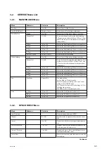
SERVICE Menu List
3-2-1.
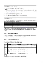
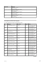
MAINTENANCE Menu
Menu
Submenu
Set value
Description
Test Saw
—
On, Off
Turns On or Off the Test Saw.
Auto BLK Balance
—
Execute, Cancel
Starts the auto black balance adjustment.
Black Shading
Setting
On, Off
Turns On or Off the black shading correction.
Channel Sel
G, B, R
Selects the channel to adjust the black shading.
(The present set values of H Saw, H Para, V Saw,
and V Para for the selected channel are displayed
automatically.)
H Saw
–99 to +99
Adjusts the black shading H Saw correction level.
H Para
–99 to +99
Adjusts the black shading H Para correction level.
V Saw
–99 to +99
Adjusts the black shading V Saw correction level.
V Para
–99 to +99
Adjusts the black shading V Para correction level.
Auto BLK Shad
Execute, Cancel
Starts the auto black shading.
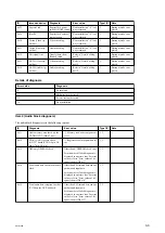
White Shading
Setting
On, Off
Turns On or Off the white shading correction.
Channel Sel
G, B, R
Select the channel to adjust the white shading. (The
present set values of H Saw, H Para, V Saw, and
V Para for the selected channel are displayed au-
tomatically.)
H Saw
–99 to +99
Adjusts the white shading H Saw correction level.
H Para
–99 to +99
Adjusts the white shading H Para correction level.
V Saw
–99 to +99
Adjusts the white shading V Saw correction level.
V Para
–99 to +99
Adjusts the white shading V Para correction level.
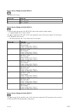
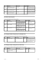
Fan
Fan Mode
Normal/Fix
Fan mode setting
Set Fan Mode to Normal usually.
Normal: Operates according to the Fan Control
setting of the OTHERS menu.
Fix: Controls the fan with a fixed voltage (8 V) for
checking fan operation.
Fan Mode is set to Normal at power-on.
Flare
G Flare
–99 to +99
Adjusts the G-ch flare correction level.
B Flare
–99 to +99
Adjusts the B-ch flare correction level.
R Flare
–99 to +99
Adjusts the R-ch flare correction level.
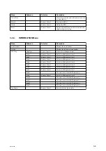
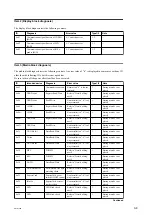
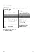
3-2-2.
RPN CORRECT Menu
Menu
Submenu
Set value
Description
Auto Detection
—
—
Starts automatic detection of RPN.
Channel
—
R, G, B
Specifies color components of pixels to be correc-
ted.
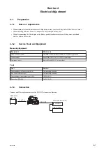
Cursor
—
On, Off
Turns On or Off the correction point indicator cur-
sor.
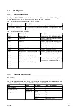
Cursor H Position
—
1 to 1920
Displays and moves the horizontal address of the
correction point indicator cursor.
Cursor V Position
—
1 to 1080
Displays and moves the vertical address of the cor-
rection point indicator cursor.
Cursor Next
—
—
Moves the correction point indicator cursor to the
next address.
Continued
PMW-300
3-3


