background image

5-4

PMW-EX1R

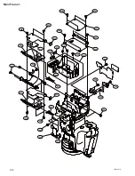
Handle Block 1

101

130

130

130

131

109

P2.6

x

 4

102

130

130

130

130

130

132

110

103

104

105

120

121

106

107

108

124

123

115

114

122

133

116

129

128

111

112

125

117

134

134

134

134

112

118

112

126

127

119

113

128

130

PTT2.6

x

 6

PTT2.6

x

 6

Summary of Contents for PMW-EX1R

Page 1: ...SOLID STATE MEMORY CAMCORDER PMW EX1R WIDE CONVERSION LENS VCL EX0877 SERVICE MANUAL 1st Edition ...

Page 2: ... dürfen nur von qualifiziertem Fachpersonal ausgeführt werden Um die Gefahr eines elektrischen Schlages Feuergefahr und Verletzungen zu vermeiden sind bei Wartungsarbeiten strikt die Angaben in der Anleitung zu befolgen Andere als die angegeben Wartungsarbeiten dürfen nur von Personen ausgeführt werden die eine spezielle Befähigung dazu besitzen AVERTISSEMENT Ce manual est destiné uniquement aux p...

Page 3: ...ligen Region und des jeweiligen Landes befolgen FÖRSIKTIGHET Fara för explosion vid felaktigt placerat batteri Byt endast mot samma eller likvärdig typ av batteri enligt tillverkarens rekommendationer När du kasserar batteriet ska du följa rådande lagar för regionen eller landet PAS PÅ Fare for eksplosion hvis batteriet ikke udskiftes korrekt Udskift kun med et batteri af samme eller tilsvarende t...

Page 4: ......

Page 5: ...placement Procedures 2 2 E 2 2 1 Lithium Battery 2 2 E 2 2 2 Case Bottom L R and Front Panel Assembly 2 2 E 2 2 3 Microphone Holder Assembly 2 4 E 2 2 4 EVF Assembly 2 4 E 2 2 5 Handle Assembly 2 5 E 2 2 6 DAP 41 Board and AU 326 Board 2 7 E 2 2 7 SW 1478 Board 2 8 E 2 2 8 Inside Panel Assembly Outside Panel Assembly 2 8 E 2 2 9 Rear Panel Assembly 2 10 E 2 2 10 Express Card Assembly 2 11 E 2 2 11...

Page 6: ...Position Setting 4 9 E 4 4 7 Operating Cursor Next 4 9 E 4 4 8 Operating Cursor Prev 4 9 E 4 4 9 Compensation Level Display 4 9 E 4 4 10 Executing Record 4 9 E 4 4 11 Executing Delete 4 10 E 4 4 12 Readout Mode Setting 4 10 E 4 4 13 Executing Reset 4 10 E 5 Spare Parts 5 1 Notes on Repair Parts 5 1 5 2 Exploded Views 5 2 5 3 Supplied Accessories 5 18 6 Block Diagrams Overall 6 2 AU 326 6 3 AXM 42 ...

Page 7: ...s are available in this model If this manual is required please contact your local Sony Sales Office Service Center Operating Instructions Supplied with unit This manual is necessary for application and operation of this unit Semiconductor Pin Assignments CD ROM Available on request This Semiconductor Pin Assignments CD ROM allows you to search for semiconductors used in Broadcast and Professional...

Page 8: ......

Page 9: ...r IEEE1394 S400 4P _ EXT VIEW _ No Signal I O Specifications 1 TPB_ I O Strobe on receive data on transmit B _ 2 TPB I O Strobe on receive data on transmit B 3 TPA_ I O Data on receive strobe on transmit A _ 4 TPA I O Data on receive strobe on transmit A AUTO MANUAL INTMIC EXT PICTURE PROFILE DC IN CH 2 AUTO MANUAL INTMIC EXT CH 1 OFF CAMERA CANCEL MENU SEL SET MEDIA PMW EX1R EXPANDED FOCUS REC RE...

Page 10: ...COMMON V O 3 33V 4 COMMON I 1 66V 5 REC I GND ON OPEN OFF 6 RET I GND ON OPEN OFF 7 SW COMMON O GND 8 FRAME GND _ 1 9 2 10 1 5 1 8 2 7 3 6 4 5 9 DC IN 2P DC JACK TYPE 4 _ EXT VIEW _ 0 HDMI OUT 19P _ EXT VIEW _ No Signal I O 1 TMDS_DATA2 O 2 TMDS_DATA2_SHIELD _ 3 TMDS_DATA2_ O 4 TMDS_DATA1 O 5 TMDS_DATA1_SHIELD _ 6 TMDS_DATA1_ O 7 TMDS_DATA0 O 8 TMDS_DATA0_SHIELD _ 9 TMDS_DATA0_ O 10 TMDS_CLOCK O 1...

Page 11: ...CN 3258 board 8 CN 3259 board 9 CN 3273 board 0 DAP 41 board DC 152 board DET 52 board DPR 311 board DR 644 board EC 68 board HN 356 board HN 360 board HN 361 board HN 363 board IF 1127 board KSW 55 board LED 491 board LED 494 board MA 183 board RE 272 board RE 273 board RM 224 board SW 1478 board SW 1484 board SWC 50 board TX 131 board VIF 46 board ...

Page 12: ...IC500 whereas the Camera Signal Processor IC IC200 performs various processing on the digital video signal supplied from the CMOS image sensor and the CAMERA MICON IC500 performs control of IC200 and other various controls such as control of the CMOS image sensor and of lens And the output digital video Y C signal is sent to the next circuit the video baseband video signal processing circuit The 1...

Page 13: ...ave control of the output systems are controlled by the built in CPU inside IC600 4 Media Recording and Playback DPR 311 Board Output from the baseband processing IC IC600 is input into the MPEG encoder decoder IC1500 The MPEG encoder decoder IC1500 is the single chip MPEG Codec IC that encodes and decodes both the high quality HD video signal and audio signal in real time It has various interface...

Page 14: ... Flexible board This board relays the audio signal between the KSW 55 board and the AU 326 board AU 326 Board Audio block This board controls the analog audio input signal processing as well as microphone 48 V power supply and serial signal Audio signal from the built in microphone on the MA 183 board is input to the balanced input amplifier IC200 and IC201 of this board Output of the balanced amp...

Page 15: ... The playback system selects CH1 CH2 or CH3 CH4 connects EE and connects TEST TONE from the Display Block depending on the data Furthermore FPGA divides the clock signal that is supplied from the Display Block to Audio Codec on the DAP 41 board INT EXT1 INT EXT2 MIC LINE 48V 1 MIC LINE 48V 2 WIND FILTER1 WIND FILTER2 COPY1to2 LINK2to1 LINK1to2 MA 183 AXM 42 VIF 46 KSW 55 HN 361 DPR 311 NH 360 AU 3...

Page 16: ...nnected to A V multi connector and connector board LED 491 Board Audio block The headphones output signal is connected to the headphones jack CN3 of the LED 491 board and the speaker output signal is connected to the speaker connector CN2 The headphones output is muted by the MUTE Q2 Q3 Switch Volume control Audio controller block Operation panel functions relating to audio signal are built into t...

Page 17: ...supply voltage at the DC IN connector is measured by the A D port on IC1001 on the RE 273 board and it is posted to the system controller as the input voltage value 6 Power system control IC1001 on the RE 273 board checks that the power switch on the PMW EX1R is turned ON and turns on the system controller of IC2900 After that it controls the power for each circuit block according to the system co...

Page 18: ...e of 17 9 V and the camera shuts down When the input power supply voltage to this circuit becomes less than 17 9 V the power supply immediately switches on with automatic recovery Input low voltage protection If the voltage is too low in the UNREG power supply the low voltage protection circuit starts operating around the set value of 10 5 V according to the control by the POWER SUPPLY MICON power...

Page 19: ...each output voltage or current for each power supply system and operate the protection circuits per block Even after the protection circuit is cleared automatic recovery is not performed and the power must be turned on again Even after short circuit is cleared the protection circuit does not recover automatically and the power must be turned on again 3 Battery information functions Battery authent...

Page 20: ... driver M2 8 J 6326 120 A Hexagon bit For torque screwdriver For tightening screw size 1 5 9 J 6325 400 A Torque driver 3 kg cm 0 3 N m For tightening screw J 6252 510 A Torque driver 6 kg cm 0 6 N m 7 432 114 11 Locking compound 200 g For preventing screw from being loosened 7 651 000 10 Sony SGL 601 50 g grease Lubricant This cable is supplied with PMW EX1R 1 4 2 Measuring Equipment Use the cali...

Page 21: ...on the PMW EX1R is turned OFF 2 Remove the cover on the USB maintenance connector 3 Use the USB connector that comes with the PMW EX1R to connect the computer and the USB maintenance connector 4 Switch the power switch to CAMERA and turn the power ON 5 Run the software for the firmware upgrade on the computer 6 When the upgrade is complete turn OFF the power and remove the USB cable 7 Attach the c...

Page 22: ...escribes the recommended replacement parts and recommended replacement time ID Part name Sony part No Recommended replacement timing 1 Eye cup 4 164 856 01 Check for deformation and deterioration from time to time 2 Lens hood 4 179 065 01 Replace it as necessary 1 2 ...

Page 23: ...ef No Address Part No Hold Current CN 3273 THP1 A 1 Side A 1 805 726 11 0 20 A 25dC THP2 A 1 Side A THP3 A 1 Side A THP4 A 1 Side A 1 7 2 Replacing Fuse w The fuse is an essential part for safe operation Replace the components with Sony parts whose part numbers appear in the manual published by Sony If the components are replaced with any parts other than the specified ones this may cause a fire o...

Page 24: ...DPR 311 board 2 The adjusted values for the LCD module are stored in the LCD module IF 1127 board but the adjusted values need to be copied to the DPR 311 board 3 The user setting values are stored in IC3250 on the DPR 311 board The user data must be stored Re store in SxS before replacing the board and it must be read Recall after replacing the board 1 8 2 Requirements on Replacement of Lens When...

Page 25: ...ontains no lead Caution Some printed circuit boards may not come printed with the lead free mark due to their particular size LEAD FREE MARK m Be sure to use the unleaded solder for the printed circuit board printed with the lead free mark The unleaded solder melts at a temperature about 40 dC higher than the ordinary solder therefore it is recommended to use the soldering iron having a temperatur...

Page 26: ...cation of flexible card cables are indicated by the circle number A and B and the location of coaxial cables with connector are indicated by the circle number C and D ASW 68 board B side AU 326 board B side DPR 311 board A side KSW 55 board A side EC 68 board B side DR 644 board A side TX 131 board B side VIF 46 board B side CN302 CN100 CN2400 CN2401 CN3401 CN3402 CN900 CN1 CN3 CN1 CN5 CN901 CN1 ...

Page 27: ...ector in the direction of arrow A to unlock and disconnect the flexible card wire Connecting 1 Insert the flexible card wire firmly as far as it will go with the insulated side up 2 Close the latch of the connector in the direction of arrow B to lock Type B Disconnecting Open the latch of the connector in the direction of arrow C to unlock and disconnect the flexible card wire Connecting 1 Insert ...

Page 28: ...he coaxial cable with connector at an angle Check that the contact on the coaxial cable with connector is free from dirt or dust When connecting the coaxial cable with connector hold the connector and align the polarity marks Then connect the coaxial cable with connector to the connector straight Disconnecting Disconnect the coaxial cable with connector while holding the connector Connecting Inser...

Page 29: ... dures Cover center assembly Battery START Handle cover upper assembly Microphone holder Tripod washer D Express card assembly RE 273 board RE 272 board TX 131 board DPR 311 board Case bottom R Battery case Prism assembly ND filter Case L assembly Case R EVF assembly Handle assembly Inside panel assembly Rear panel assembly Outside panel assembly Battery lid Lithium battery Front panel assembly Ca...

Page 30: ...s fine pitch coaxial cables Be careful when arranging the cable When disconnecting the coaxial cable with connector do not attempt to remove by pulling the cable Be sure to hold the connector to remove 2 2 1 Lithium Battery 1 Remove the screw and remove the lithium battery lid 2 Remove the lithium battery 3 Reinstall the lithium battery by reversing the steps of removal Lithium battery lid Three c...

Page 31: ...nt panel assembly by reversing the steps of removal n When installing the front panel assembly check if the position of the slide switch S2 on the SW 1478 board matches the position of the SHUTTER knob Two dowels Front panel assembly SW 1478 board Slide switch S2 Shutter knob SW 1478 board Front panel assembly ...

Page 32: ...emoval Microphone holder assembly B2 6 x 6 2 2 4 EVF Assembly 1 Remove the microphone holder assembly Refer to Section 2 2 3 2 Remove the four screws 3 Disengage the two claws on the front of the handle cover upper assembly first Then remove the rear of the handle cover upper assembly from the EVF assembly n Be careful not to drop the rubber SW key M2 x 4 black M2 x 4 black Claws Rubber SW key Han...

Page 33: ...teps of removal Handle cover rear assembly Claws Fin M2 x 3 silver M2 x 4 black M2 x 4 black EVF assembly HN 363 board DR 644 board CN3 Rear accessory shoe 2 2 5 Handle Assembly 1 Refer to Sections from 2 2 3 to 2 2 4 and disassemble the unit up to EVF Assembly removal 2 Remove the four screws of a and remove the cover center assembly 3 Disconnect the connector CN2 on the HN 361 board from the con...

Page 34: ... disconnect the coaxial cable with connector from the connector CN700 on the DPR 311 board 8 Remove the handle assembly while pulling off the flexible card wire 30 core m The coaxial cable with connector uses fine pitch coaxial cables Be careful when arranging the cable When disconnecting the coaxial cable with connector do not attempt to remove by pulling the cable Be sure to hold the connector t...

Page 35: ...ws of b and discon nect the connector CN200 on the DAP 41 board from the connector CN101 on the AU 326 board 6 Remove the screw of c 7 While pushing case R lightly in the direction of the arrow remove the DAP 41 board Case R CN102 CN200 CN101 CN104 CN107 CN103 Bottom support assembly Harnesses Harness SWC 50 board AU 326 board CN101 HN 356 board DAP 41 board M2 x 3 silver M2 x 3 silver M2 x 4 blac...

Page 36: ...SW 1478 board and remove the SW 1478 board 4 Reinstall the SW 1478 board by reversing the steps of removal SW 1478 board Harness M2 x 3 silver CN1 2 2 8 Inside Panel Assembly Outside Panel Assembly 1 Refer to Sections from 2 2 1 to 2 2 5 and disassemble the unit up to Handle Assem bly removal 2 Remove the two screws of a and one screw of b and remove the inside panel assembly a b Inside panel asse...

Page 37: ...e harness holder 5 Disconnect the harness and coaxial cable with connector from the connectors CN1 and CN3 on the VIF 46 board e CN3 CN1 VIF 46 board Outside harness holder Harness Coaxial cable with connector e M2 x 3 silver 6 Peel off the tape from the inside of the outside panel assembly 7 Disconnect the harness from the connector CN2 on the VIF 46 board 8 Reinstall the inside panel assembly ou...

Page 38: ...oval 3 Remove the two screws of a that fix the SW 1484 board 4 Remove the four screws of b 5 Disconnect the harness from the connector CN1 on the RE 272 board 6 Disconnect the CN 3273 flexible board from the connector CN101 on the ASW 68 board 7 Reinstall the rear panel assembly by reversing the steps of removal CN 3273 board RE 272 board CN1 Harness ASW 68 board CN101 Rear panel assembly SW 1484 ...

Page 39: ...y removal 3 Disconnect the coaxial cable with connectors from connectors on the two EC 68 boards 4 Remove the two screws Coaxial cable with connector slot A Coaxial cable with connector slot B EC 68 board M2 x 3 silver M2 x 3 silver 5 Remove the two screws and remove the express card assembly in the direction of the arrow 6 Reinstall the express card assembly by revers ing the steps of removal Exp...

Page 40: ...exible board from the connector CN1 on the RE 273 board and remove the RE 273 board CN1 Top plate RE 273 board RE 272 board CN 3259 board M2 x 3 silver M2 x 3 silver Claw 7 Remove the two screws of c and remove the inside button holder 8 Remove the four screws of d and remove the DD CON holder 9 Disconnect the harnesses from the connector CN2 on the RE 272 board 10 Disconnect the CN 3258 flexible ...

Page 41: ...ews of b and remove the bottom support assembly n When replacing the battery case assembly be sure to also replace the battery case gasket and the inside bottom gasket at the same time b M2 x 3 silver a M2 x 4 black a a a a a Battery case assembly Bottom support assembly b Battery case gasket Inside bottom gasket 5 Remove the screw of c and remove the CN 3273 board from the i Link holder 6 Remove ...

Page 42: ... the screw of g and remove the main harness holder 13 Disconnect the coaxial cable from the coaxial connector 14 Remove the two screws of h remove the coaxial connector 15 Remove the four screws of i remove the bottom plate h g h i i i g M2 x 3 silver h M2 x 3 silver i M2 x 3 silver Coaxial cable Coaxial connector Bottom plate Main harness holder k k k B2 x 3 silver Coaxial cable TX 131 board 16 D...

Page 43: ... main heat spreader Main heat spreader Adhered portion Rear main frame Heat transfer sheet top M2 x 4 silver M2 x 4 silver 5 Disconnect the CN 3258 board CN 3259 board CN 3273 board and HN 356 board from the connectors on the DPR 311 board 6 Disconnect the flexible boards of prism assembly from the three connectors on the DPR 311 board 7 Disconnect the flexible card wire 30 core and two coaxial ca...

Page 44: ...al 3 Remove the three screws of a and remove the rear main frame 4 Remove the two screws of b and remove the HN 360 board in the direction of the arrow a b a a M2 x 4 silver b M2 x 3 silver Rear main frame HN 360 board 5 Disconnect the SWC 50 board from the connector CN104 on the DAP 41 board 6 Disconnect the HN 360 board from the connector CN2 on the AU 326 board HN 360 board SWC 50 board DAP 41 ...

Page 45: ... the case L assembly Case L assembly ND filter knob Lever Flexible boards of prism assembly c c c M2 x 4 black 2 2 15 Case R 1 Refer to Sections from 2 2 1 to 2 2 5 and disassemble the unit up to Handle Assem bly removal 2 Refer to Sections from 2 2 8 to 2 2 14 and disassemble the unit up to Case L Assembly removal 3 Remove the screw of a and remove the cover 4 Remove the one screw of b and two sc...

Page 46: ...C MOS flexible sheet dowels Positioning holes 2 2 17 ND Filter 1 Refer to Sections from 2 2 1 to 2 2 5 and disassemble the unit up to Handle Assem bly removal 2 Refer to Sections from 2 2 8 to 2 2 16 and disassemble the unit up to Prism Assembly removal 3 Disconnect the harness from the connector on the ND filter 4 Remove the three screws and remove the ND filter by drawing the lever block of the ...

Page 47: ...oning hole of the main frame Front frame Lens unit Positioning hole Positioning pin P2 6 x 5 P2 6 x 5 P2 6 x 5 2 2 19 DR 644 Board 1 Refer to Sections from 2 2 3 to 2 2 5 and disassemble the unit up to Handle Assem bly removal 2 Disconnect the harnesses from the connector CN2 on the DP 644 board 3 Remove the two screws and remove the DR 644 board 4 Reinstall the DR 644 board by reversing the steps...

Page 48: ...ard by reversing the steps of removal Connector cover LED 491 bracket LED 491 board CN11 LED 491 bracket M6 nut LED 491 board M2 x 3 silver M2 x 3 silver 2 2 21 Speaker 1 Refer to Sections from 2 2 3 to 2 2 5 and disassemble the unit up to Handle Assem bly removal 2 Refer to Section 2 2 20 and disassemble the unit up to LED 491 board removal 3 Remove the two screws and remove the speaker holder n ...

Page 49: ...on the KSW 55 board 4 Remove the four screws and remove the KSW 55 board CN3 CN2 M 2 x 3 silver Control switch block AXM 42 board KSW 55 board CN6 CN5 CN7 Rubber SW key 5 Disconnect the control switch block from the connector CN4 on the KSW 55 board 6 Disconnect the HN 361 board from the connector CN1 on the KSW 55 board 7 Reinstall the KSW 55 board and HN 361 board by reversing the steps of remov...

Page 50: ... the blind plate in the direction of arrow B 5 Remove the two screws 6 Pull out the harness KSW53 MA161 and the harness KSW53 RM213 from the hole on the handle in the direction of arrow C 7 Remove the microphone unit assembly in the direction of arrow D n Be careful not to hook or damage the har nesses 8 Reinstall the microphone unit assembly by reversing the steps of removal C D Tapping M2 x 5 bl...

Page 51: ...he screw of b and remove the microphone cover Microphone unit Microphone cover Microphone case Tapping M2 x 5 black Tapping M2 x 5 black Microphone unit RM 224 board Harness KSW53 RM213 c Tapping M2 x 5 black d Tapping M2 x 5 black MA 183 board Harness KSW53 MA161 c MA cushion CN1 CN1 CN3 d CN2 6 Disconnect the harness KSW53 MA161 CN3 and the microphone unit harness CN1 CN2 from the MA 183 board 7...

Page 52: ...over top 4 Disconnect the harnesses CN1 from the connector on the DET 52 board 5 Remove the screw of b and remove the DET 52 board and the DET44 fit plate 6 Remove the two screws of c and remove the DET 52 board from the DET44 fit plate 7 Reinstall the DET 52 board by reversing the steps of removal Hinge cover top M2 x 4 black M1 4 x 2 5 silver M1 4 x 2 5 silver LCD block DET 52 board DET44 fit pl...

Page 53: ...ws and remove the LCD cabinet in the direction of arrow B 4 Disconnect the coaxial cable with connector from the IF 1127 board 5 Remove the four screws and the LCD pack ing and remove the 3 5 inch LCD assembly 6 Reinstall the 3 5 inch LCD assembly by reversing the steps of removal Connector IF 1127 board 3 5 inch LCD assembly M2 x 3 silver LCD packing Coaxial cable with connector LCD bezel B A M2 ...

Page 54: ...rip cover Fig 3 2 Install the new cap START STOP by align ing its notch with the protrusion of the grip cover Fig 3 Installing the grip cover Reinstall the grip cover by reversing the steps of removal Replacing the grip belt 1 Separate the grip belt from the buckle and remove the pad Fig 4 2 Pull it off the grip belt from the grip cover Fig 4 3 Install the new grip belt by reversing the steps of r...

Page 55: ...CE dedicated menus Menu name Description MAINTENANCE Adjustment of parameters RPN CORRECT Operations regarding the RPN correction INFORMATION Information display on the particular PMW EX1R and self diagnostics The MAINTENANCE menu and the RPN CORRECT menu can be operated in the CAMERA mode 3 1 3 Displaying the SERVICE Menu To display the SERVICE menu the following operations are needed 1 Close the...

Page 56: ...ly H Saw _99 to 99 Adjusts the white shading H Saw correction level H Para _99 to 99 Adjusts the white shading H Para correction level V Saw _99 to 99 Adjusts the white shading V Saw correction level V Para _99 to 99 Adjusts the white shading V Para correction level Flare G Flare _99 to 99 Adjusts the G ch flare correction level B Flare _99 to 99 Adjusts the B ch flare correction level R Flare _99...

Page 57: ...s the self diagnostic type Type2 Item1 Execute Executes self diagnostic Item 1 Cancel Item2 Execute Executes self diagnostic Item 2 Cancel Item3 Execute Executes self diagnostic Item 3 Cancel Item4 Execute Executes self diagnostic Item 4 Cancel Item5 Execute Executes self diagnostic Item 5 Cancel Item6 Execute Executes self diagnostic Item 6 Cancel Item7 Execute Executes self diagnostic Item 7 Can...

Page 58: ...sor block Diagnosis of lens CMOS block and camera block Item2 Display block Diagnosis of video signal system LCD and base band signal processing Item3 Media block Diagnosis of media recording and playback encoder decoder memory card i LINK and USB interface Item4 Audio block Diagnosis of audio input and output Item5 System controller block Diagnosis of system controller system Item6 Power block Di...

Page 59: ...diagnosis appears Example of the display for results of self diagnosis Press the CANCEL button joystick or jog dial while displaying the result of self diagnosis to return to the INFORMATION menu The results of self diagnosis The result of self diagnosis is composed of the diagnostic item ID DiagID for the Item and Try Success and Result for the item The result of the self diagnosis for each item ...

Page 60: ...Therefore make sure not to touch rings during the diagnosis The focus ring does not turn 0x08 Number of RPN 1 Exceeding RPN max 1 2 _ registrations check number 0x09 Reading Writing data test to 1 CMOS Read Write NG 1 2 _ CMOS block video signal or CMOS video signal bus connection test between bus NG CMOS and camera signal processor IC 0x0a Communication test of 5 Camera signal processor 1 2 _ cam...

Page 61: ...ck requires a long time 0x06 USB Device Register 1 Error 1 only _ Read Write check 0x09 i Link Register Read 1 Error 1 only _ Write check 0x0B USB Host Register Read 1 Error 1 only _ Write check 0x14 PIFC POWSW 1 Error 1 only _ 0x15 SPA POWSW 1 Error 1 only _ 0x12 MPEG encoder decoder 1 Error 1 only _ IC Data Read Write 0x20 NOR FlashROM data 1 Error 1 only _ consistency check 0x23 Slot A LED blin...

Page 62: ...is detected in the version matching test upgrade again to a compatible version Contact your local Sony Sales Office Service Center for information on versions Item6 Power block diagnosis Power block diagnosis analyzes the following contents ID Diagnosis description Error value Type 1 2 Note 0x01 Power switch readout 1 Cannot readout power 1 2 Power switch must be set to switch CAMERA 4 Cannot diag...

Page 63: ... line communication 1 Test pattern checking failure 1 2 _ test in recording direction in the 2 Sequence error direction from base band processing IC to AVIT signal processing IC 11 0x93 LPCM signal line communication 1 Test pattern checking failure 1 2 _ test in playback direction in the 2 Sequence error direction from AVIT signal processing IC to base band processing IC When an error is detected ...

Page 64: ...start up 17004 The media block does not start up 17005 Abnormality in the start up process of the image processor block 17006 Abnormality in the start up process of the display block 17007 Abnormality in the start up process of the media block 17014 Abnormality in lens communication Check the connection with the lens unit If there is no defect replace the lens unit 17015 Abnormality in the media b...

Page 65: ...4 2 1 Service Tools and Equipment Refer to Section 1 4 for detail of the service tools and equipment used for the adjustments 4 2 2 Connection Connect an HD waveform monitor to the SDI OUT terminal of the unit 4 3 MAINTENANCE Menu The MAINTENANCE menu enables setting for image device and setting parameters that must be set uniquely to each PMW EX1R for correction of non uniformity between the resp...

Page 66: ...rected areas Do not change the Black Shading correction values to any values other than 0 unless it is necessary 1 Setting The Black Shading setting menu can be used to turn Black Shading correction On or Off The Black Shading correction is turned On automatically when the power is turned On 2 Channel Select The Channel Select menu enables selection of the channel G ch or B ch or R ch to execute t...

Page 67: ... parabola correction level m The White Shading adjustment cannot be executed for the correct adjustment values if the object pattern has non uniformity or if other conditions such as lens iris setting and zoom setting are not correctly satisfied Use a full white pattern for the White Shading adjustment having uniform brightness over the entire area If a full white pattern having uniform brightness...

Page 68: ...shading correction linear increase and decrease level V Para The V Para menu enables the vertical Parabola white shading correction sensitivity correction at the vertical center with respect to both ends level White shading adjustment method Preparation Connect an HD waveform monitor to the SDI OUT terminal HD waveform monitor setting RGB mode Focus Shoot an all white pattern over the entire frame...

Page 69: ...ustment Procedure 1 Adjust lens iris until white level becomes approximately 100 After that open the lens iris by two stops 2 Select waveform of the signal at the center of grayscale signal on a waveform monitor 3 Adjust R Flare G Flare and B Flare until the black levels on both sides of the center white in all of the R G and B channels to a unity level Align black level all channels to that of th...

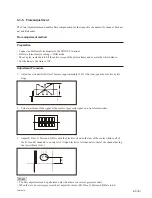
Page 70: ...nged after focus adjustment The result of Auto FB Adjust is saved When the Auto FB Adjust menu is selected the Execute and Cancel choices appear In addition selecting Execute starts automatic adjustment of flange back FB Flange Focal Length adjustment method Preparation Upgrade the firmware to the newest version Prepare the Flange Back Chart and place it at the distance of 3 meters far from the ca...

Page 71: ...ELE end and adjust the camera position so that center of the chart stays approxi mately in the center of a screen Item Setting Lens ZOOM POSITION _ TELE ZOOM SERVO _ FOCUS _ FULL MANUAL IRIS _ OPEN GAIN 0dB _ WHITE BAL ATB _ FULL AUTO OFF _ 4 Enter the SERVICE menu and select MAINTENANCE Auto FB Adjust Then execute Auto FB Adjust 5 Wait until Auto FB Adjust is complete 6 Restart the camera Check a...

Page 72: ...ection mode for a pixel when the pixel is registered by manual registration of RPN The Correction Mode selecting Concealment and Compensation For the manual registration of RPN select Concealment 4 4 3 Channel Setting The Channel menu enables selection of the channel R ch or G ch or B ch to execute Record of RPN pixel on in the manual registration of RPN When the RPN cursor indicating location of ...

Page 73: ...er the present position in the ascending order of the addresses during the manu al registration of RPN If multiple RPN positions have the same address in the ascending order of the Cursor V Position the RPN cursor moves in the ascending order of the Cursor H Position 4 4 8 Operating Cursor Prev The Cursor Prev menu enables the user to move the RPN cursor position to the next already registered RPN...

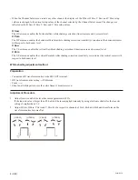
Page 74: ...actory and the RPN data is manually registered cannot be deleted by the Reset When the Reset menu is selected the Execute and Cancel choices appear In addition selecting Execute starts reset of RPN RPN manual registration procedure 1 Set the Video Format to HQ 1080 60i 2 Set the Readout Mode to Frame To facilitate viewing the RPN position on a monitor screen 3 Set the lens iris to CLOSE 4 Adjust G...

Page 75: ...y and improvement 3 Stock of Parts Parts marked with o at SP Supply Code column of the spare parts list may not be stocked Therefore the delivery date will be delayed 4 Harness Harnesses with no part number are not registered as spare parts Section 5 Spare Parts 5 1 補修部品注意事項 1 安全重要部品 警告 印のついた部品は安全性を維持するために重要 な部品です したがって 交換する時は必ず指定 の部品を使ってください 2 部品の共通化 ソニーから供給する補修用部品は セットに使われて いるものと異なることがあります これは部品...

Page 76: ...5 2 PMW EX1R Handle Cover and EVF Assembly 5 2 Exploded Views 1 14 7 13 15 2 21 10 17 3 18 4 12 6 20 8 9 9 9 19 9 11 9 9 16 5 ...

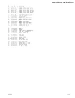
Page 77: ...E ASSY 7 1 811 033 11 s LCD MODULE 8 1 873 733 11 s BOARD FP 776 FLEXIBLE 9 3 080 203 31 s SREW M2 LOCK ACE P2 10 3 165 904 01 s WASHER SCREW STOPPER 11 3 278 644 01 s XDCAM EMBLEM 12 3 285 383 03 s COVER CONNECTOR 13 3 288 585 02 s CASE PANEL 14 3 288 586 02 s LID PANEL 15 3 288 591 01 s SHEET VF PROTECTION 16 3 302 492 01 s SPRING COMPRESSION 17 3 657 657 02 s SCREW M5 18 3 878 256 03 s RUBBER S...

Page 78: ...k 1 101 130 130 130 131 109 P2 6 x 4 102 130 130 130 130 130 132 110 103 104 105 120 121 106 107 108 124 123 115 114 122 133 116 129 128 111 112 125 117 134 134 134 134 112 118 112 126 127 119 113 128 130 PTT2 6 x 6 PTT2 6 x 6 ...

Page 79: ... TAPPING P2 114 3 276 443 01 s SPEAKER CUSHION 115 3 276 875 03 s HANDLE COVER LOW 116 3 276 876 01 s SPEAKER GRILLE 117 3 276 877 01 s DAMPER LCD 118 3 276 881 01 s LCD SUPPORT 119 3 278 663 02 s KSW 53 BRACKET 120 3 278 665 02 s KNOB XLR SW 121 3 278 666 02 s RAIL XLR SW 122 3 278 667 03 s HOLDER SPEAKER 123 3 282 659 02 s SHEET HANDLE REAR 124 3 452 727 01 s SHEET SPEAKER HOLDER 125 3 678 684 0...

Page 80: ...5 6 PMW EX1R Handle Block 2 201 221 225 221 224 202 230 203 204 205 229 206 207 209 210 208 211 227 212 212 215 212 219 212 212 212 213 213 228 226 222 213 213 213 214 218 223 220 214 216 217 ...

Page 81: ...211 1 966 994 11 s HARNESS DPR311 LCD 212 3 080 203 31 s SREW M2 LOCK ACE P2 213 3 080 206 21 s SCREW TAPPING P2 214 3 086 368 31 s SCREW M1 4 LOCK ACE P2 215 3 276 867 01 s PLATE BLIND 216 3 276 871 01 s BEZEL LCD 217 3 276 872 01 s PACKING LCD 218 3 276 874 01 s HINGE COVER TOP 219 3 276 878 02 s LCD CABINET 220 3 278 640 01 s SHEET PANEL BLIND 221 3 278 656 02 s MIC SIDE GRILLE 222 3 278 657 01...

Page 82: ...5 8 PMW EX1R Inside Panel and Bottom Cover 301 302 304 306 313 314 311 305 303 309 310 310 310 308 304 307 304 304 312 304 304 304 304 ...

Page 83: ... LOCK ACE P2 304 3 056 233 21 s SREW M2 LOCK ACE P2 305 3 080 203 51 s SREW M2 LOCK ACE P2 306 3 278 639 02 s JACK COVER 307 3 288 392 01 s WASHER D TRIPOD 308 3 604 795 01 s CAP BNC 309 3 701 439 21 s WASHER 310 3 968 729 52 s SCREW M2 LOCK ACE P2 311 4 164 565 01 s USB COVER 312 4 164 566 01 s CASE BOTTOM L 313 4 164 567 01 s CASE BOTTOM R 314 4 164 568 01 s LID LITHIUM BATERY ...

Page 84: ...Outside Panel and Rear Panel 401 412 429 423 418 411 420 419 419 419 419 419 419 413 413 410 421 414 415 415 415 422 430 402 403 404 419 419 419 405 426 427 428 406 415 407 419 419 419 419 419 425 408 424 416 417 409 ...

Page 85: ...66 992 11 s HARNESS TX131 VIF46 412 1 966 993 11 s HARNESS SUB ASW68 LED491 413 1 966 995 12 s HARNESS SUB VIF46 ASW68 414 3 080 203 21 s SREW M2 LOCK ACE P2 415 3 056 233 21 s SREW M2 LOCK ACE P2 416 3 278 316 01 s TAPE C 417 3 701 443 01 s WASHER 5 418 3 729 013 21 s SCREW M1 4X2 5 WASHERHEAD P 419 3 968 729 52 s SCREW M2 LOCK ACE P2 420 4 164 570 01 s RELEASE BUTTON BT 421 4 164 572 01 s COVER ...

Page 86: ...5 12 PMW EX1R Main Frame 1 501 508 508 509 509 501 507 507 502 504 503 505 510 506 508 508 508 508 508 508 511 514 514 512 513 511 508 508 508 508 508 508 508 508 ...

Page 87: ...ATTERY CASE ASSY 505 X 2515 748 1 s SUPPORT BOTTOM ASSY 506 1 780 570 11 s TERMINAL BOARD BATTERY 507 1 966 990 11 s HARNESS DPR311 EC68 508 3 968 729 52 s SCREW M2 LOCK ACE P2 509 4 164 571 01 s SHEET RADIATION 1 5 C 510 4 164 598 01 s SHEET RADIATION BOTTOM 511 4 164 656 01 s SHEET RADIATION 1 A 512 4 166 648 01 s BATTERY CASE GASKET 513 4 170 734 01 s INSIDE BOTTOM GASKET 514 3 080 203 31 s SCR...

Page 88: ...5 14 PMW EX1R Main Frame 2 601 612 617 618 619 622 620 621 623 624 627 627 627 626 625 625 611 602 603 604 605 606 607 615 609 609 608 613 613 622 613 610 616 616 614 616 616 616 616 616 616 616 ...

Page 89: ...90 11 s HARNESS DPR311 EC68 611 1 966 991 11 s HARNESS SUB TX131 VIF46 612 1 966 992 11 s HARNESS TX131 VIF46 613 3 056 233 21 s SCREW M2 LOCK ACE P2 614 3 080 203 01 s SREW M2 LOCK ACE P2 615 3 278 727 01 s BNC COVER 616 3 968 729 52 s SCREW M2 LOCK ACE P2 617 4 164 571 01 s SHEET RADIATION 1 5 C 618 4 164 619 01 s SHEET HEAT TRANSFER MAIN 619 4 164 620 01 s SHEET HEAT TRANSFER TOP 620 4 164 626 ...

Page 90: ...EX1R Front Block P2 6 x 5 P2 6 x 5 P2 6 x 5 701 721 721 702 703 717 716 718 719 720 720 723 704 722 722 722 722 705 722 722 722 722 722 713 706 710 707 715 726 715 711 725 708 714 714 714 714 709 712 714 714 724 ...

Page 91: ...11 1 788 703 13 s ND FILTER OPTICAL 712 1 965 711 11 s HARNESS SUB SE912 AU313 713 1 965 713 11 s HARNESS SUB AU313 SW1375 714 3 056 233 21 s SCREW M2 LOCK ACE P2 715 3 080 206 21 s SCREW TAPPING P2 716 3 281 730 01 s SWC 47 ADHESIVE SHEET 717 3 281 751 01 s SHEET HN 338 ADHESIVE 718 3 284 472 01 s CUSHION ASSIGN 719 3 285 955 01 s CMOS PROTECTION SHEET A 720 3 285 956 01 s CMOS PROTECTION SHEET B...

Page 92: ... 782 476 13 s CORD POWER CN 1pc 1 828 544 12 s CORD CONNECTION USB 1pc 1 829 414 22 s CABLE CONNECTION COMPONENT 1pc 1 831 553 22 s CORD CONNECTION AV MULTIPLE 1pc 3 278 903 01 s SHORUDER BELT 1pc 4 130 649 04 s CD ROM UTILITY SOFTWARE 1pc 4 163 183 01 s MANUAL INSTRUCTION J 1pc 4 163 183 11 s MANUAL INSTRUCTION CE E UC 1pc 4 163 183 21 s MANUAL INSTRUCTION CN 1pc 4 164 150 01 s CD ROM INSTRUCTION...

Page 93: ...4 6 7 DC 152 DC IN connector 6 9 DET 52 LCD switch 6 8 DPR 311 MAIN board 6 4 5 6 7 DR 644 EVF driver 6 8 EC 68 ExpressCard slot 6 5 HN 356 DPR DAP relay board 6 3 4 6 7 HN 360 AU HN relay board 6 3 HN 361 KSW HN relay board 6 3 HN 363 DR EVF relay board 6 8 KSW 55 Handle switch 6 3 8 LED 491 LED CACHE 6 11 LED 494 Headphone 6 11 MA 183 Internal MIC 6 3 RE 272 DC DC converter 6 9 RE 273 DC DC conv...

Page 94: ...rRM RTC BATTERY SWITCHING POWER CON i LINK CONT USB DEVICE COMPONENT OUT i HDV ExpressCard SLOT FLASH IC203 CONFIG SDI P S DRIVER IC801 DAC IC704 705 ADC FLASH TEMP SDRAM IC1301 SDRAM IC1405 CONFIG FPGA AUDIO DSP AD DA M DDR M DDR DDR2 DR 644 DPR 311 RM 224 KSW 55 SWC 50 ASW 68 1 2 DAP 41 1 3 RE 273 EC 68 EC 68 EVF LCD MIC1 MIC2 SPEAKER HEADPHONE AUDIO IN CH1 CH2 VCXO PLL X300 301 IC301 307 VCXO P...

Page 95: ...US DRIVER 1 9 11 2 4 6 8 10 IC208 13 12 2 I O1 3 3 I O2 5 4 5 7 13 12 8 IC206 SERIAL PARALLEL SDA SCL 5 1 3 6 IRQ FOUT 7 X1 X2 VBAT IC100 RTC X100 32 768kHz 1 2 1 2 3 Q100 Q101 IC101 HPOUT1R HPOUT1L HP_R HP_L SP SP SPKOUTLN SPKOUTLP F4 G3 B1 A1 EXT_1 CN200 17 EXT_2 18 LINE_1 19 LINE_2 20 COPY1to2 21 12dB_1 CN200 25 12dB_2 27 LINK_1_A 28 LINK_2_A 29 WIND_FIL_1 24 WIND_FIL_2 26 48V_1 22 BIAS DC 48V ...

Page 96: ...SE_CS_X A19 CS7 IM_CAM_XRESET AA13 PQ2 D19 BS ADV E5 D16 CS0 AA19 WAIT Y18 P87 AB9 INT6 AA4 INT3 AC8 INT2 AB7 INT1 Y7 O_GP_V AC4 O_EXT_OHB_H_X AB8 INT4 AC9 INT5 A19 O_SIRQ A18 O_CPU_WAIT E19 I_CLK_CPU IM_CAM_XRESET D14 I_SRST_X IM_RISE_CS_X D20 I_CPU_CS_X IM_RD B19 I_CPU_RD_X IM_WE0 D19 I_CPU_WR_X F4 RST G7 WAIT F1 CE B21 RD F1 OE J2 D17 WE0 WE F5 C20 RD WR CAS F7 D18 RAS RAS F8 C19 CAS CKE F3 C21...

Page 97: ... DQS0 3 MD_TRINO_BMDQS0 3 66 54 72 48 OMADB0 1 251 185 2 2 BA0 1 MD_TRINO_OMADBB0 1 69 30 DQ0 31 22 62 63 95 64 96 65 97 89 55 90 56 91 57 58 16 38 76 75 105 74 104 73 103 83 47 82 46 81 45 80 44 29 116 28 117 27 195 26 113 242 90 174 89 172 173 241 88 263 110 264 108 112 19 109 18 7 8 6 99 96 95 97 98 RAS 31 CAS 70 11 OMCLK 10 OMCLKX CK 50 CK 85 CKE 7 IHCLK 57 IBCLK 35 CS 100 WE 101 86 NC2 16 XTA...

Page 98: ... 3 I_CLK_DDR CKE G1 CS H7 WE G7 12 A0 12 DP_O_DDR_ADDR0 12 J8 J9 K7 K9 K1 K3 J1 J2 J3 H1 J7 H2 H3 32 4 DM0 3 DP_B_DDR_DM0 3 DP_B_DDR_DATA0 31 K8 K2 F8 F2 4 DQS0 3 DP_B_DDR_DQS0 3 L8 L2 E8 E2 2 BA0 1 DP_O_DDR_BA0 1 H8 H9 DQ0 31 R8 P7 P8 N7 N8 M7 M8 L7 L3 M2 M3 N2 N3 P2 P3 R2 A8 B7 B8 C7 C8 D7 D8 E7 E3 D2 D3 C2 C3 B2 B3 A2 RAS G9 CAS G8 CK G2 CK G3 CKE G1 CS H7 WE G7 IC1101 MDDR RAM A1 7 36 74 XTIN_...

Page 99: ...TO_TX_MLN_WE0 DQMLL 104 DPR_TO_TX_MLN_RD 103 DPR_TO_TX_MLN_RD WR 106 DPR_TO_TX_MLN_CS6 108 DPR_TO_TX_700_INT 89 DPR_TO_TX_MLN_RESET 26 SY_TCK 25 SY_TRST 24 SY_TDO 23 SY_RTCK 22 SY_TMS 21 SY_TDI IC1716 1718 DELAY D3001 SY_ 2 5V HN 356 3 4 CN1 91 93 94 CN2 91 93 94 24 A0 23 A1 24 4 A0 3 DPR_TO_TX_MLN_DAT0 7 8 D0 7 H2 H3 G3 H4 J5 G5 J6 H7 G2 J3 G4 J4 H5 G6 H6 J7 DQ0 15 D0 15 D0 15 D0 15 G1 F1 E1 D1 B...

Page 100: ...L_OPEN CLOSE CN3 1 4 CN1 1 1 4 EVF MODULE S1 ZOOM MODULE S2 CN1 22 CN6 2 SDA0 18 P32 32 P06 30 I2C_SDA CN2 CN2 CN2 2 S1 SWITCH IC100 LOCAL uCOM ZOOM SPEED 8 SW_ZOOM_A H CN6 8 9 SW_ZOOM_B OFF SW_ZOOM_A SW_ZOOM_B CN6 9 21 1 SCL0 17 I2C_SCL I2C_SDA I2C_SCL I2C_SDA I2C_SCL 8 SW_UCON_RESET SW_UCON_RESET 1 3 RESET P43 40 124 6 P70 29 P71 28 2 5 7 5 SW_UCN_RESET 3 CN4 2 3 5 S100 H L OFF P05 31 SW_REC_SS ...

Page 101: ..._IM CN200 81 84 Q225 L208 SY DOWN DET Q238 239 D205 D218 220 D15 18 D202 208 D16 19 201 204 207 Q227 229 24 SW_SY_1P2V 4 6V_IM CN200 37 38 4 6V CN200 3 16 Q216 L200 Q27 IC13 SWITCHING CONTROL L3 L2 Q14 16 L1 Q200 208 26 SW_IM_4P6V 4 6V_DP CN200 17 18 Q217 L201 Q201 209 35 SW_DP_4P6V 4 6V_SY CN200 33 34 Q243 L212 Q244 245 IC18 DC DC CONV 3 1 4 27 SW_SY_4P6V SW_IM_1P2V SW_SY_1P2V SW_IM_4P6V SW_DP_4P...

Page 102: ...5V SW_DP_M4P6V 4 6V_DP CN1 57 58 23 CN2 CN2 CN2 CN2 CN2 22 18 41 IM_EN 42 43 ME_EN SY_EN DP_EN 39 44 41 40 PWR_ON HOLD 52 57 EVER5_ON OFF H_SHUTDOWN CN2 49 28 GP_140 29 GP_141 GP_50 GP_51 25 29 7 56 27 CN1 CN1 26 18 6 10 14 16 4 Q7 EVER 5V Q1002 Q1003 Q1000 CN1 PWR_WAKEUP 18 64 Q1001 D17 20 CN2 46 DOWN_DET_IM 45 DOWN_DET_DP 44 DOWN_DET_ME 40 DOWN_DET_SY 38 BATT_ID_DATA 1 57 58 UNSW_UNREG IC10 DC D...

Page 103: ... 29 SW_EXCHANGE 7 P40 5 5 5 P03 59 AIN6 50 AU_AUDIO_VOL1 CN100 6 AIN7 49 AU_AUDIO_VOL2 2 7 S2 AU VOL MODULE POWER SW MODULE P04 58 P71 28 LED_RRTALLY CN103 9 CN104 9 LED SW Q1 Q1 MUTE DRIVE Q200 202 26 26 SP SP 26 CN103 CN104 6 27 27 SP SP 27 CN1 CN2 35 35 36 36 7 6 7 CN2 CN3 2 SPEAKER HEADPHON NC 1 SW 1484 LED 491 D1 LED SW Q1 D2 5V 5V P130 57 LED_CACHE CN301 3 CN1 3 LED SW LED 494 D1 2 5V P141 6...

Page 104: ...N_WE0 DQMLL DPR_TO_TX_MLN_CS6 DPR_TO_TX_700_INT DPR_TO_TX_700_WAIT DPR_TO_TX_700_B150DET DPR_TO_TX_MLN_RESET DPR_TO_TX_MLN_CKI02 88 DPR_TO_TX_700_RESET 107 RM_VIDEO_VBS 19 20 21 22 23 24 25 26 27 DPR_TO_TX_MLN_DAT0 7 90 97 SY_MLN_DAT0 7 7 14 RM_VIDEO_Y 2 TX_TO_VIF_HDMI_PBPR0 9 30 21 CN901 U18 TX_TO_VIF_HDMI_CLK 20 CN901 M13 TX_TO_VIF_HDMI_HSYNC 19 N13 TX_TO_VIF_HDMI_VSYNC 18 H6 EX3_TO_TX_TC_IN 28 ...

Page 105: ...U 326 Inside SW SWC 50 Gain 20p 8p 4p 30p 30p 100p 100p 100p 100p 80p p 0 8 100p p 0 8 p 0 8 p 0 0 1 p 0 0 1 6p 14p 14p 2p 45p 45p 45p 12p 4p 4p 6p 12p 10p 10p 6p 6p 30p 30p 15p 30p 50p 6p 5p 60p 60p 3p 5p 160p 160p 2p 80p 80p 80p 80p 80p 80p 30p 30p 30p 30p 30p 30p 30p 40p 10p Zebra Peaking Display Shot_trans Assign CN 3258 CN 3273 HN 363 p 0 0 1 60p 60p 50p Headphone AUDIO IN CH 1 CH 2 SDI OUT F...

Page 106: ......

Page 107: ......

Page 108: ...Sony Corporation PMW EX1R UC PMW EX1R E PMW EX1R J PMW EX1R CE PMW EX1R CN J E 9 968 701 01 Printed in Japan 2009 11 16 2009 ...

Reviews: