background image

27

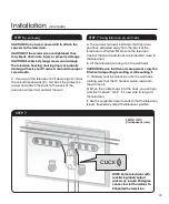
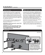
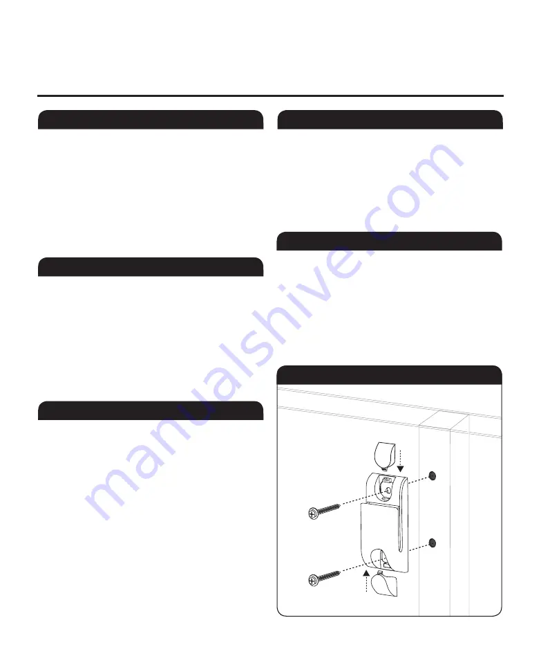
G.  use your electric drill to screw in the lag bolts to 
firmly attach the wall hook to the wall. For wood stud 
construction, you will be screwing the lag bolts into 
the stud. For concrete walls, you will be screwing the 
lag bolts into the anchors. Be careful not to over-
tighten the lag bolts. 
H.  Replace the top and bottom caps on the wall hook. 

Installation 

(cOnTInuED)

STEP 3: 

Mark the bottom screw location

STEP 4: 

Attach wall hook to the wall

STEP 4 

(continued)

STEPS 3 & 4

STEP 5: 

  Attach TV harness to television

A.  Remove the top and bottom caps from the wall 
hook (A).  
B.  Place the wall hook on the wall surface, aligning 
the top screw hole with the top screw location 
you’ve marked.  If necessary, use a carpenter’s level 
to confirm that the wall hook is aligned vertically.  
c.  Make a small pencil mark through the bottom 
screw hole to indicate the bottom screw location. 

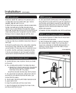
A.  Locate the two screw location marks you made 
on the wall. 
B.  For concrete walls, perform the following steps:

a.   Attach the 1/2-inch masonry bit to your electric 

drill (hammer drill recommended) and drill 

holes two inches (50 mm) deep.

b.   Set the concrete anchors (Q) into the holes.

c.  For wood stud construction, attach the 1/8-inch 
wood bit to your electric drill and drill holes two 
inches (50 mm) deep.
D.  For all walls, attach the #2 Phillips head driver bit 
to your electric drill.
E.  Align the wall hook with the screw holes.  
F.  Insert the lag bolts (P) through the holes in the 
wall hook and into the wall.  

STEP 2 

(continued)

television meets the wall stud.  If necessary, use 
a carpenter’s level to confirm that your mark is 
properly aligned with the stud.
K.  Mark the top screw location. Measure down from 
the Top center Mark by the Top Screw Distance 
(Line 3 in your calculation on the previous page)
and make another pencil mark on the wall. For wood 
stud construction, use a carpenter’s level to confirm 
that your mark is properly aligned with the stud.

A.  Locate the top pair of “VESA” mount screw holes 
on the back of the television. 
B.  The TV harness (B) includes a pair of mounting 
bars connected by a cable.  The mounting bars 
have holes indicated at 100, 200, 300 and 400 mm 
spacing.  Line up the bars with the “VESA” mount 
screw holes that match.  

cOnTInuED


WAll / sTud

Summary of Contents for PROFORMA PROFORMAWM46

Page 1: ...Wall Mount Installation Guide PROFORMAWM46 English Instructions Page 2 Spanish Instructions Page 12 French Instructions Page 22 ...

Page 2: ...Thank you for purchasing the ProForma WM 46 Wall Mount It s an easy fast and effective way to mount flat panel televisions of screen sizes up to 46 inches viewable area measured diagonally Maximum television weight is 80 lbs ...

Page 3: ... water waste and any other plumbing before drilling or installing fasteners If the Wall Mount or the TV is not installed correctly the wall hook or TV may fall and cause serious injury or property damage This unit is designed to be mounted only on walls of concrete or wood stud construction Make sure that mounting screws are anchored into the center of the studs Use of an edge to edge stud finder ...

Page 4: ... Install the TV on a wall that is both vertical and flat Installing the TV on an overhanging unstable or uneven wall may cause the TV to fall and cause injury or property damage Do not allow the AC power cord or the connecting cable to be pinched If the AC power cord or the connecting cable is pinched between the unit and the wall or is bent or twisted by force the internal conductors may become e...

Page 5: ... Harness Quantity 1 Spacers Quantity 2 Self Adhesive Pads Quantity 2 M4 x 22mm Quantity 4 M5 x 22mm Quantity 4 M5 x 35mm Quantity 4 M8 x 25mm Quantity 4 M8 x 30mm Quantity 4 Lag Bolt Quantity 2 Concrete Anchor Quantity 2 M8 x 40mm Quantity 4 SK5 16 5 x 5 4 x 1 5 mm Quantity 8 SK5 16 5 x 8 5 x 1 5 mm Quantity 8 M6 x 20mm Quantity 4 M6 x 24mm Quantity 4 M6 x 35mm Quantity 4 ...

Page 6: ...ocation on the wall D Locate the VESA mount screw holes on the back of the television These will form a rectangle or square that measures 100 200 300 or 400 mm approximately 4 8 12 or 16 inches across E Locate the top pair of VESA mount screw holes Measure the distance from the center of one screw hole to the top of the television Write the measurement in the space below LINE 1 Write down the dist...

Page 7: ...bit to your electric drill hammer drill recommended and drill holes two inches 50 mm deep b Set the concrete anchors Q into the holes C For wood stud construction attach the 1 8 inch wood bit to your electric drill and drill holes two inches 50 mm deep D For all walls attach the 2 Phillips head driver bit to your electric drill E Align the wall hook with the screw holes F Insert the lag bolts P th...

Page 8: ...ay fall and cause injury or property damage If they are over tightened they may break and cause injury or property damage A If you want the television to sit parallel to the wall install the spacers C with the supplied machine screws Your Wall Mount is supplied with several sets of machine screws parts E F G H I J K L and M These cover in a range of diameters and lengths Consult your TV s operatin...

Page 9: ... of the television E Use the carpenter s level to confirm that the television is level If necessary adjust the television s position Step 7 front of TV transparent view Click Step 6 continued CAUTION Do not use a power drill to attach the spacers to the television CAUTION If the screws are over tightened they may break and cause injury or property damage CAUTION Excessively long screws can damage ...

Page 10: ...les from the back of the television A To use the kickstands carefully reach behind the television and extend the metal kickstands toward the wall B To return the television to normal position carefully reach behind the television and fold the metal kickstands up toward the television Step 8 A Step 8 B Kickstand extended wall wall normal position ...

Page 11: ... of purchase in the form of a bill of sale or receipted invoice which is evidence that the unit is within the warranty period Components repaired or replaced are warranted for the remainder of the original warranty period only REPAIR OR REPLACEMENT AS PROVIDED UNDER THIS LIMITED WARRANTY IS THE EXCLUSIVE REMEDY OF THE CONSUMER THE MANUFACTURER SHALL NOT BE LIABLE FOR ANY INCIDENTAL OR CONSEQUENTIA...

Page 12: ...sing the ProForma WM 46 Wall Mount It s an easy fast and effective way to mount flat panel televisions of screen sizes up to 46 inches viewable area measured diagonally Maximum television weight is 80 lbs Spanish Instructions ...

Page 13: ... water waste and any other plumbing before drilling or installing fasteners If the Wall Mount or the TV is not installed correctly the wall hook or TV may fall and cause serious injury or property damage This unit is designed to be mounted only on walls of concrete or wood stud construction Make sure that mounting screws are anchored into the center of the studs Use of an edge to edge stud finder ...

Page 14: ... Install the TV on a wall that is both vertical and flat Installing the TV on an overhanging unstable or uneven wall may cause the TV to fall and cause injury or property damage Do not allow the AC power cord or the connecting cable to be pinched If the AC power cord or the connecting cable is pinched between the unit and the wall or is bent or twisted by force the internal conductors may become e...

Page 15: ...V Harness Quantity 1 Spacers Quantity 2 Self Adhesive Pads Quantity 2 M4 x 22mm Quantity 4 M5 x 22mm Quantity 4 M5 x 35mm Quantity 4 M8 x 25mm Quantity 4 M8 x 30mm Quantity 4 Lag Bolt Quantity 2 Concrete Anchor Quantity 2 M8 x 40mm Quantity 4 SK5 16 5 x 5 4 x 1 5 mm Quantity 8 SK5 16 5 x 8 5 x 1 5 mm Quantity 8 M6 x 20mm Quantity 4 M6 x 24mm Quantity 4 M6 x 35mm Quantity 4 ...

Page 16: ...location on the wall D Locate the VESA mount screw holes on the back of the television These will form a rectangle or square that measures 100 200 300 or 400 mm approximately 4 8 12 or 16 inches across E Locate the top pair of VESA mount screw holes Measure the distance from the center of one screw hole to the top of the television Write the measurement in the space below LINE 1 Write down the dis...

Page 17: ...bit to your electric drill hammer drill recommended and drill holes two inches 50 mm deep b Set the concrete anchors Q into the holes C For wood stud construction attach the 1 8 inch wood bit to your electric drill and drill holes two inches 50 mm deep D For all walls attach the 2 Phillips head driver bit to your electric drill E Align the wall hook with the screw holes F Insert the lag bolts P th...

Page 18: ...may fall and cause injury or property damage If they are over tightened they may break and cause injury or property damage A If you want the television to sit parallel to the wall install the spacers C with the supplied machine screws Your Wall Mount is supplied with several sets of machine screws parts E F G H I J K L and M These cover in a range of diameters and lengths Consult your TV s operati...

Page 19: ... of the television E Use the carpenter s level to confirm that the television is level If necessary adjust the television s position Step 7 front of TV transparent view Click Step 6 continued CAUTION Do not use a power drill to attach the spacers to the television CAUTION If the screws are over tightened they may break and cause injury or property damage CAUTION Excessively long screws can damage ...

Page 20: ...les from the back of the television A To use the kickstands carefully reach behind the television and extend the metal kickstands toward the wall B To return the television to normal position carefully reach behind the television and fold the metal kickstands up toward the television Step 8 A Step 8 B Kickstand extended wall wall normal position ...

Page 21: ... of purchase in the form of a bill of sale or receipted invoice which is evidence that the unit is within the warranty period Components repaired or replaced are warranted for the remainder of the original warranty period only REPAIR OR REPLACEMENT AS PROVIDED UNDER THIS LIMITED WARRANTY IS THE EXCLUSIVE REMEDY OF THE CONSUMER THE MANUFACTURER SHALL NOT BE LIABLE FOR ANY INCIDENTAL OR CONSEQUENTIA...

Page 22: ...sing the ProForma WM 46 Wall Mount It s an easy fast and effective way to mount flat panel televisions of screen sizes up to 46 inches viewable area measured diagonally Maximum television weight is 80 lbs French Instructions ...

Page 23: ... water waste and any other plumbing before drilling or installing fasteners If the Wall Mount or the TV is not installed correctly the wall hook or TV may fall and cause serious injury or property damage This unit is designed to be mounted only on walls of concrete or wood stud construction Make sure that mounting screws are anchored into the center of the studs Use of an edge to edge stud finder ...

Page 24: ... Install the TV on a wall that is both vertical and flat Installing the TV on an overhanging unstable or uneven wall may cause the TV to fall and cause injury or property damage Do not allow the AC power cord or the connecting cable to be pinched If the AC power cord or the connecting cable is pinched between the unit and the wall or is bent or twisted by force the internal conductors may become e...

Page 25: ...V Harness Quantity 1 Spacers Quantity 2 Self Adhesive Pads Quantity 2 M4 x 22mm Quantity 4 M5 x 22mm Quantity 4 M5 x 35mm Quantity 4 M8 x 25mm Quantity 4 M8 x 30mm Quantity 4 Lag Bolt Quantity 2 Concrete Anchor Quantity 2 M8 x 40mm Quantity 4 SK5 16 5 x 5 4 x 1 5 mm Quantity 8 SK5 16 5 x 8 5 x 1 5 mm Quantity 8 M6 x 20mm Quantity 4 M6 x 24mm Quantity 4 M6 x 35mm Quantity 4 ...

Page 26: ...location on the wall D Locate the VESA mount screw holes on the back of the television These will form a rectangle or square that measures 100 200 300 or 400 mm approximately 4 8 12 or 16 inches across E Locate the top pair of VESA mount screw holes Measure the distance from the center of one screw hole to the top of the television Write the measurement in the space below LINE 1 Write down the dis...

Page 27: ...bit to your electric drill hammer drill recommended and drill holes two inches 50 mm deep b Set the concrete anchors Q into the holes C For wood stud construction attach the 1 8 inch wood bit to your electric drill and drill holes two inches 50 mm deep D For all walls attach the 2 Phillips head driver bit to your electric drill E Align the wall hook with the screw holes F Insert the lag bolts P th...

Page 28: ...may fall and cause injury or property damage If they are over tightened they may break and cause injury or property damage A If you want the television to sit parallel to the wall install the spacers C with the supplied machine screws Your Wall Mount is supplied with several sets of machine screws parts E F G H I J K L and M These cover in a range of diameters and lengths Consult your TV s operati...

Page 29: ... of the television E Use the carpenter s level to confirm that the television is level If necessary adjust the television s position Step 7 front of TV transparent view Click Step 6 continued CAUTION Do not use a power drill to attach the spacers to the television CAUTION If the screws are over tightened they may break and cause injury or property damage CAUTION Excessively long screws can damage ...

Page 30: ...les from the back of the television A To use the kickstands carefully reach behind the television and extend the metal kickstands toward the wall B To return the television to normal position carefully reach behind the television and fold the metal kickstands up toward the television Step 8 A Step 8 B Kickstand extended wall wall normal position ...

Page 31: ... of purchase in the form of a bill of sale or receipted invoice which is evidence that the unit is within the warranty period Components repaired or replaced are warranted for the remainder of the original warranty period only REPAIR OR REPLACEMENT AS PROVIDED UNDER THIS LIMITED WARRANTY IS THE EXCLUSIVE REMEDY OF THE CONSUMER THE MANUFACTURER SHALL NOT BE LIABLE FOR ANY INCIDENTAL OR CONSEQUENTIA...

Page 32: ...le or in part without written permission is prohibited Features and specifications subject to change without notice Sony the Sony logo and the Sony make believe logo are trademarks of Sony Printed in USA 6 11 Sony Electronics Inc 16530 Via Esprillo San Diego CA 92127 ...

Reviews: