


PRS-505
42
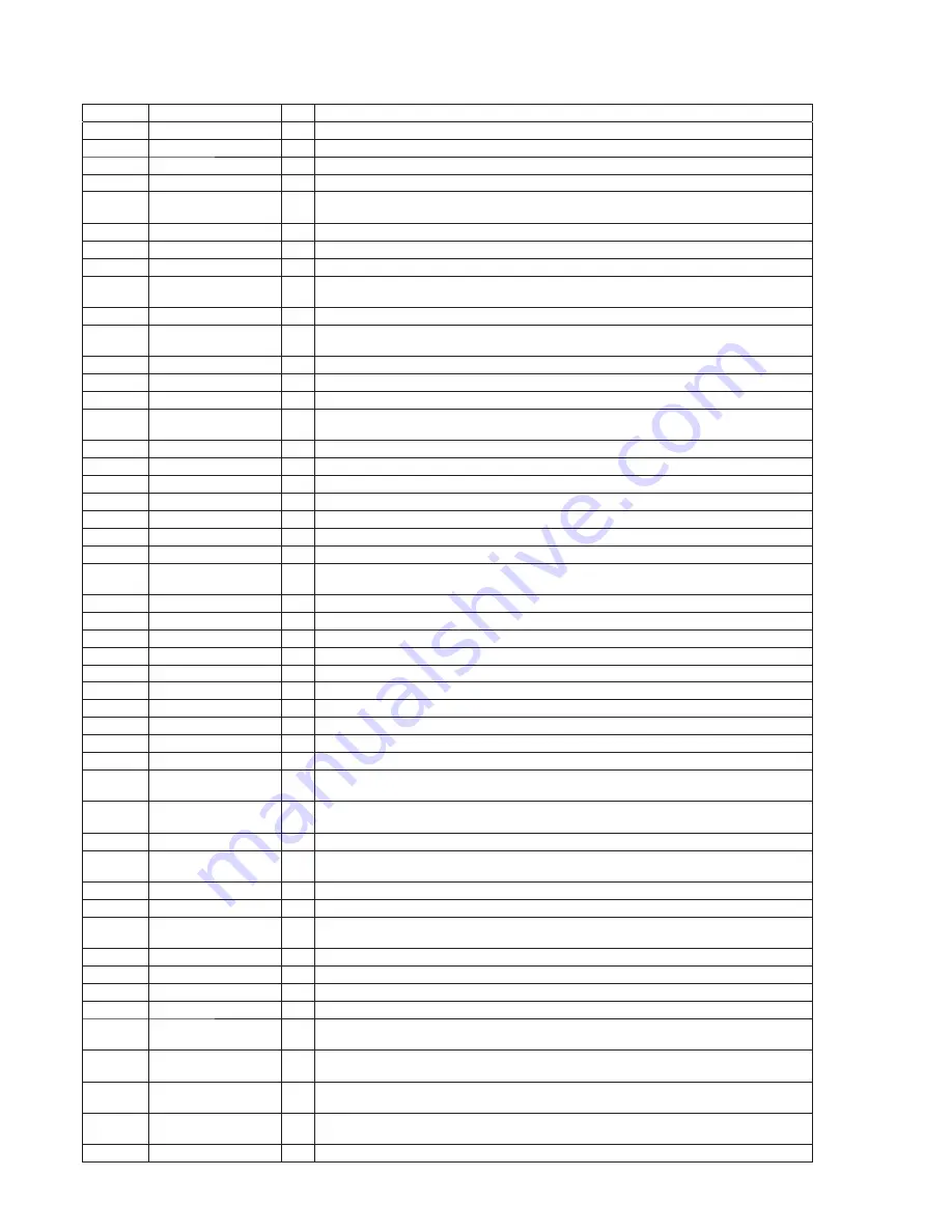
Pin No.
Pin Name
I/O
Description
K5
NVDD1
-
Power supply terminal (+2.9V)
K6, K7
VSS
-
Ground terminal
K8
NVDD1
-
Power supply terminal (+2.9V)
K9
VSS
-
Ground terminal
K10
D1
I/O
Two-way data bus with the memory stick duo/SD memory card controller, USB controller,
NAND
fl
ash memory, SD-RAM and NOR
fl
ash memory
K11
BOOT2
I
System boot mode select signal input terminal
K12
TDI
I
Test data input terminal Not used
K13
BIG_ENDIAN
I
Not used
K14
XRESET-OUT
O
Reset signal output to the audio D/A converter, memory stick duo/SD memory card control-
ler, USB controller, NAND
fl
ash memory and NOR
fl
ash memory
K15
XTAL32K
O
System clock output terminal (32.768 kHz)
L1, L2
A10, A9
O
Address signal output to the memory stick duo/SD memory card controller, SD-RAM and
NOR
fl
ash memory
L3, L4
D17, D18
I/O
Two-way data bus with the SD-RAM
L5, L6
NVDD1
-
Power supply terminal (+2.9V)
L7
XCS5
O
Chip select signal output terminal
L8
D2
I/O
Two-way data bus with the memory stick duo/SD memory card controller, USB controller,
NAND
fl
ash memory, SD-RAM and NOR
fl
ash memory
L9
PA20
O
Not used
L10, L11
VSS
-
Ground terminal
L12
POR
I
Power on reset signal input from the sub CPU "H": reset
L13
VSS
-
Ground terminal
L14
XTAL16M
O
System clock output terminal Not used
L15
EXTAL32K
I
System clock input terminal (32.768 kHz)
M1
D16
I/O
Two-way data bus with the SD-RAM
M2 to M4
D15, D13, D10
I/O
Two-way data bus with the memory stick duo/SD memory card controller, USB controller,
SD-RAM and NOR
fl
ash memory
M5
XEB3
O
Byte strobe signal output terminal Not used
M6
NVDD1
-
Power supply terminal (+2.9V)
M7, M8
XCS4, XCS1
O
Chip select signal output terminal
M9
PA18
-
Not used
M10
XRW
O
Read/write enable signal output terminal
M11
VSS
-
Ground terminal
M12
BOOT3
I
System boot mode select signal input terminal
M13
QVDD2
-
Power supply terminal (+1.9V)
M14
XRESET-IN
I
Master reset signal input from the sub CPU "L": reset
M15
EXTAL16M
I
System clock input terminal Not used
N1, N2
A8, A7
O
Address signal output to the memory stick duo/SD memory card controller, USB controller,
SD-RAM and NOR
fl
ash memory
N3
D12
I/O
Two-way data bus with the memory stick duo/SD memory card controller, USB controller,
SD-RAM and NOR
fl
ash memory
N4
XEB0
O
Byte strobe signal output terminal Not used
N5, N6
D9, D8
I/O
Two-way data bus with the memory stick duo/SD memory card controller, USB controller,
SD-RAM and NOR
fl
ash memory
N7, N8
XCS3, XCS0
O
Chip select signal output terminal
N9
PA17
-
Not used
N10
D0
I/O
Two-way data bus with the memory stick duo/SD memory card controller, USB controller,
NAND
fl
ash memory, SD-RAM and NOR
fl
ash memory
N11, N12
DQM2,DQM0
O
Data enable signal output to the SD-RAM
N13
SDCK0
O
Clock enable signal output to the SD-RAM
N14
TRISTATE
I
Not used
N15
XTRST
I
Test reset signal input terminal Not used
P1
D14
I/O
Two-way data bus with the memory stick duo/SD memory card controller, USB controller,
SD-RAM and NOR
fl
ash memory
P2
A1
O
Address signal output to the memory stick duo/SD memory card controller, USB controller
and NOR
fl
ash memory
P3 to P6
A2 to A5
O
Address signal output to the memory stick duo/SD memory card controller, USB controller,
SD-RAM and NOR
fl
ash memory
P7, P8
D6, D5
I/O
Two-way data bus with the memory stick duo/SD memory card controller, USB controller,
NAND
fl
ash memory, SD-RAM and NOR
fl
ash memory
P9, P10
MA10, MA11
O
Address signal output to the SD-RAM
Summary of Contents for PRS-505
Page 52: ...PRS 505 MEMO 52 ...
Page 73: ...MEMO PRS 505 21 ...


