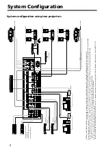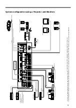
10
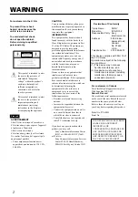
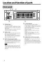
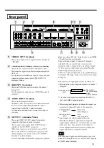
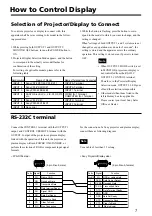
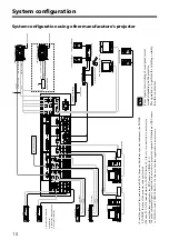
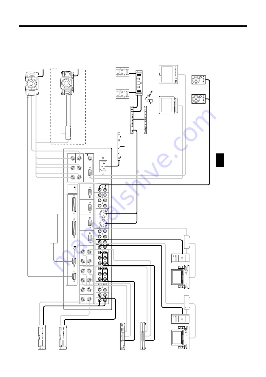
• Even if the power of this unit is turned OFF by the power distributor or power conditioner, the POWER
STANDBY function of the projector can be performed.
•
When an PLC-XF10 (manufactured by SANYO Electric Co., Ltd.) etc. is connected, it is necessary to
connect the video signal cable too. (
A
Connect to VIDEO IN-1)
When the component signal is connected, it is necessary to prepare the external RGB distributor. (
B
Connect
to VIDEO IN-1 and COMPUTER IN-1.) In this case, the video signal cable is not necessary.
Video input: Six inputs are
the maximum.
(In case of the channels 5 and 6
are used for VIDEO IN.)
System configuration using other manufacuture’s projector
System configuration
It may require for switching of cross-point several
seconds depending on the projector.
This operation is to perform the switching certainly,
then this is not failure.
Note
34
VIDEO INPUT
OUTPUT1
RGB INPUT
COMPONENT/VIDEO IN
P
ARALLEL
I/O
OUTPUT
1
OUTPUT2/
MONIT
O
R
AUDIO INPUT
VIDEO
R/R-Y
G/Y
SYNC/HD
VD
B/B-Y
7
89
1
0
Y
C
B
/
B-Y
Y
3
2
1
4
C
R
/
R-Y
5
6
~ AC
IN
VIDEO
VIDEO
OUT
IN
OUTPUT2/MONIT
OR
VIDEO
PROJECT
OR
MONIT
O
R
OUTPUT2 MODE
RGB/Y
R-Y
B-Y
OUTPUT
1
CONTROL
OUTPUT
2
CONTROL
REMOTE
L
R
12
CENTER
WOOFER
FRONT
REAR
78
91
0
56
RL
L
R
CENTER
WOOFER
FRONT
REAR
L
R
CENTER
WOOFER
FRONT
REAR
L
R
L
R
RS-232C
C
R
/
R-Y
C
B
/
B-Y
T
O
AC
POWER
RGB INPUT
TERMINAL
AUDIO
VIDEO
RGB
RGB DISTRIBUT
OR
COMPUTER
AUDIO
AUDIO
RGB
PROJECT
OR by except SONY
AUDIO MIXER
POWER DISTRIBUT
OR
VTR
VTR
RGB
COMPOSITE VIDEO
RS-232C
WIRELESS RECEIVER
T
O
AC
POWER
RGB DISTRIBUT
OR
COMPUTER
MONIT
OR SPEAKER
MUL
TI SCANER DISPLA
Y
FOR PC
VIDEO MONIT
O
R
FRONT
SPEAKER(L)
FRONT
SPEAKER(R)
POWER AMPLIFIER
SYSTEM CONTROLLER
PROJECT
OR by except SONY
RGB DISTRIBUT
OR
RGB
RGB INPUT
TERMINAL
COMPONENT
INPUT
TERMINAL
Y
R-Y
B-Y
T
O
AC
POWER
COMPONENT
DVD PLA
YER
BS DIGIT
A
L
TUNER
COMPONENT
VIDEO
AUDIO
VIDEO INPUT
TERMINAL
A
B


