background image

4

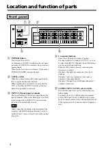
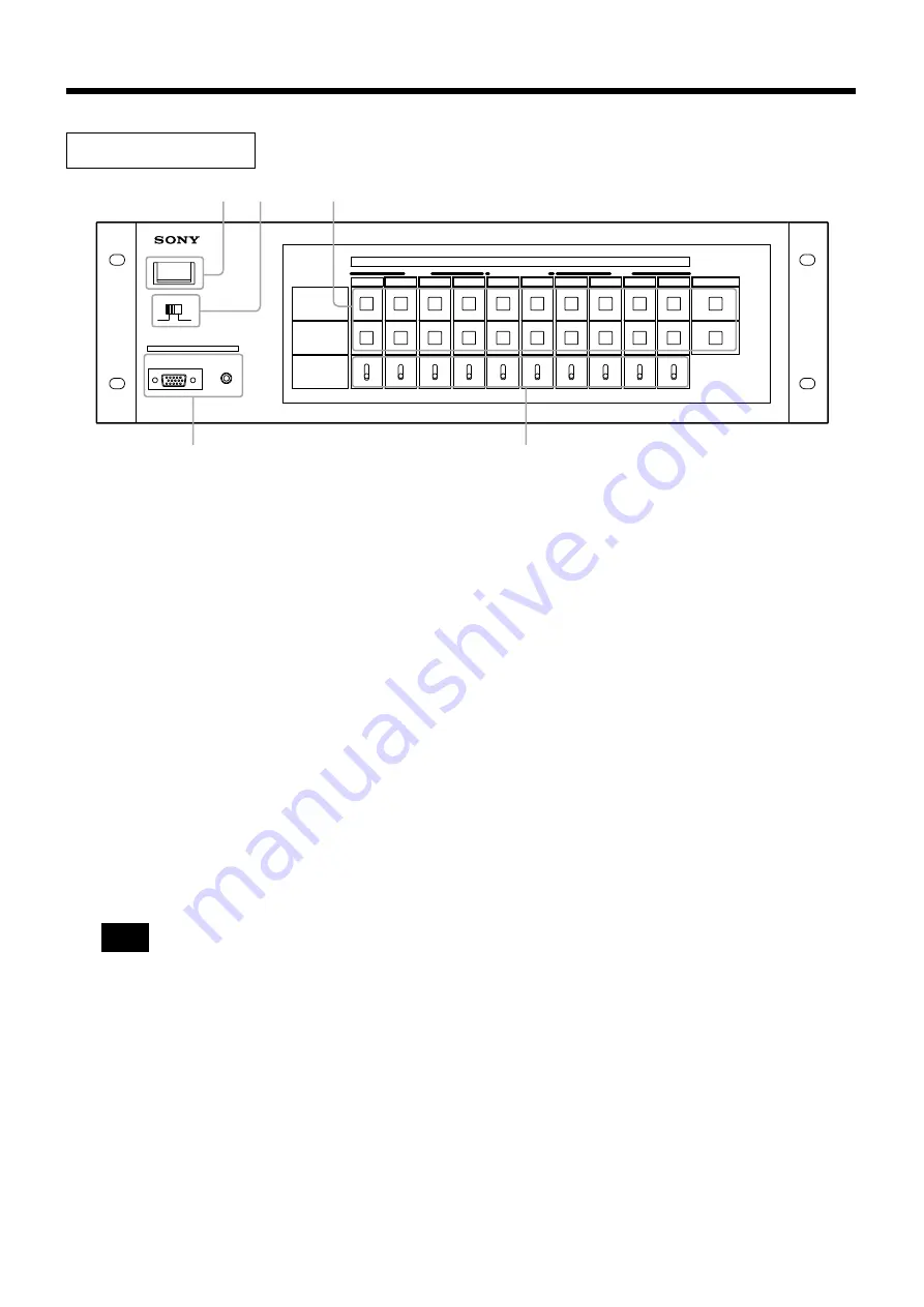
Location and function of parts

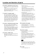
Front panel

1

POWER button

Press to turn this unit ON.
At this moment, RS-232C terminal on the rear panel
transmits a POWER ON command to the projector or
plasma display.
When the power of this unit is turned off, transmits a
POWER STANDBY command to them.

2

LOCK switch

When this switch is turned ON, button operation on
the crosspoint buttons are prohibited.
When operating the unit remotely by using the RS-
232C or PARALLEL INPUT terminal on the rear
panel, miss-operation is prevented.

3

INPUT 10 front input terminals

These are RGB and AUDIO front input terminal for
laptop computer. When either RGB input or AUDIO
input is plugged in with INPUT 10 selected mode,
front input is automatically selected.

When connecting the display output terminal of the
computer with RGB front input terminal, be sure to
use the D-sub 15 pin 

˜

 D-sub 15 pin, fully connec-

tion cable.

4

Crosspoint buttons

These select from input to output of signals.
The input signal to be output to OUTPUT 1 or 2 can
be select from INPUT 1 through 10 and OFF buttons,
and the selected button lights up.
When the OFF button is pressed, video and audio
signals are not output.
Channels 1 through 4 are composite video input
channels.
Channels 5 and 6 are component video input or
composite video input channel.
Channels 7 through 10 are RGB input channels for
computer respectively.

5

AUDIO INPUT LEVEL select switch

The reference input level can be switched between
0dBu/-10dBu.
In general, the level is 0 dBu for digital equipment
such as DVD and CD, and -10dBu for video equip-
ment. For details, please refer to the operation manual
of the equipment to be connected, and set it appropri-
ately.

Note

LOCK

POWER

OFF

ON

RGB

INPUT 10

OUTPUT 1

AUDIO

OUTPUT 2

/MONITOR

INPUT

VIDEO

RGB

COMPONENT/VIDEO

MATRIX SWITCHER PVS-R102

0dBu

-10dBu

1

2

3

4

5

6

7

8

9

10

OFF

0dBu

-10dBu

0dBu

-10dBu

0dBu

-10dBu

0dBu

-10dBu

0dBu

-10dBu

0dBu

-10dBu

0dBu

-10dBu

0dBu

-10dBu

0dBu

-10dBu

AUDIO INPUT LEVEL

1

4

2

5

3

Summary of Contents for PVS-R102

Page 1: ...PVS R102 Matrix Switcher 2 347 513 22 1 Operating Instructions Before operating the unit please read this manual thoroughly and retain if for future reference 2002 Sony Corporation ...

Page 2: ...o frequency energy and if not installed and used in accordance with the instructions may cause harmful interference to radio communications However there is no guarantee that interference will not occur in a particular installation If this equipment does cause harmful interference to radio or television reception which can be determined by turning the equipment off and on the user is encouraged to...

Page 3: ...eed conversion system Signal is also input to the LCD projector or plasma display through the common cable with the computer RGB signals which realizes the less connection cable at the same time Although a composite cable may be additionally required for some models 10 bit digital 3 dimentional Y C separation circuit is adopted for the NTSC signal conversion Component signal is applicable to high ...

Page 4: ... tion cable 4 Crosspoint buttons These select from input to output of signals The input signal to be output to OUTPUT 1 or 2 can be select from INPUT 1 through 10 and OFF buttons and the selected button lights up When the OFF button is pressed video and audio signals are not output Channels 1 through 4 are composite video input channels Channels 5 and 6 are component video input or composite video...

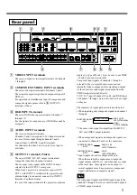
Page 5: ...imultaneous input of component and composite signals please refer to 5 OUTPUT 1 terminals Video 3 RGB INPUT terminals These are RGB video input terminals of channels 7 through 10 For the signal of a computer etc 15k RGB cannot be accepted 4 AUDIO INPUT terminals These are audio input terminals Channels 5 and 6 correspond to 5 1 channel surround In case of stereo input through channels 5 and 6 conn...

Page 6: ...of the projector or plasma display models when switched between different video signals it may occur that picture become deteriorate or need time to display etc however it is not a failure of unit AC Inlet Connect the supplied power cord Location and function of parts 6 OUTPUT 2 MONITOR terminals Video These are RGB Y R Y B Y output and VIDEO output terminals It outputs video signal of the INPUT c...

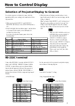
Page 7: ...E switch is set to MONITOR projector or display is not controlled from the RS 232C OUTPUT 2 CONTROL terminal Therefore in the Projector Display Selection mode OUTPUT 2 LED goes off and the selection is impossible Other models than those listed in the left table may be also applicable Please contact your local Sony Sales Office or Dealer RS 232C terminal Connect the CONTROL 1 terminal with the OUTP...

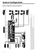
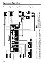
Page 8: ...se of the channels 5 and 6 are used for VIDEO IN System configuration using two projectors 3 4 VIDEO INPUT OUTPUT1 RGB INPUT COMPONENT VIDEO IN PARALLEL I O OUTPUT 1 OUTPUT2 MONITOR AUDIO INPUT VIDEO R R Y G Y SYNC HD VD B B Y 7 8 9 10 Y C B B Y Y 3 2 1 4 C R R Y 5 6 AC IN VIDEO VIDEO OUT IN OUTPUT2 MONITOR VIDEO PROJECTOR MONITOR OUTPUT2 MODE RGB Y R Y B Y OUTPUT 1 CONTROL OUTPUT 2 CONTROL REMOTE...

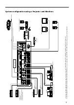
Page 9: ... VIDEO R R Y G Y SYNC HD VD B B Y 7 8 9 10 Y C B B Y Y 3 2 1 4 C R R Y 5 6 AC IN VIDEO VIDEO OUT IN OUTPUT2 MONITOR VIDEO PROJECTOR MONITOR OUTPUT2 MODE RGB Y R Y B Y OUTPUT 1 CONTROL OUTPUT 2 CONTROL REMOTE L R 1 2 CENTER WOOFER FRONT REAR 7 8 9 10 5 6 R L L R CENTER WOOFER FRONT REAR L R CENTER WOOFER FRONT REAR L R L R RS 232C C R R Y C B B Y TO AC POWER DVD PLAYER BS DIGITAL TUNER AUDIO COMPON...

Page 10: ... not failure Note 3 4 VIDEO INPUT OUTPUT1 RGB INPUT COMPONENT VIDEO IN PARALLEL I O OUTPUT 1 OUTPUT2 MONITOR AUDIO INPUT VIDEO R R Y G Y SYNC HD VD B B Y 7 8 9 10 Y C B B Y Y 3 2 1 4 C R R Y 5 6 AC IN VIDEO VIDEO OUT IN OUTPUT2 MONITOR VIDEO PROJECTOR MONITOR OUTPUT2 MODE RGB Y R Y B Y OUTPUT 1 CONTROL OUTPUT 2 CONTROL REMOTE L R 1 2 CENTER WOOFER FRONT REAR 7 8 9 10 5 6 R L L R CENTER WOOFER FRON...

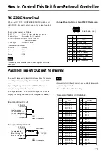
Page 11: ...inal For external switches be sure to use non lock type such as tactile type switch Use a cable of less than 50 m long Example of Input Circuit Example of Output Circuit Output terminals Nos 2 through 12 Nos 14 through 24 12V MAX 20mA MAX N GND Nos 1 13 and 25 Parallel Input Output terminal PVS R102 PVS R102 Note Note Pin No Function 1 GND 2 crosspoint 1 1 3 crosspoint 1 2 4 crosspoint 1 3 5 cross...

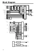
Page 12: ...B Y R Y B Y RGB HD VD Y R Y B Y RGB HD VD Y R Y B Y 2 1 RGB Switch OUTPUT1 AUDIO Switch OUTPUT2 AUDIO Switch INPUT5 L RL C W Mix INPUT2 4 7 10 L R INPUT2 4 7 10 L R INPUT6 L R RL RR W INPUT5 R RR C W Mix INPUT6 L RL C W Mix INPUT6 R RR C W Mix Sub CPU for Display control MAIN CPU Sub CPU for Display control 6 1 Video Switch 3 1 Component Video Switch 5 1 Wide Band RGB Switch NTSC PAL Color Decorde...

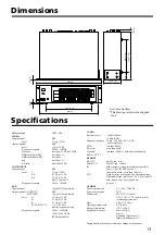
Page 13: ...z reference T H D less than 0 005 S N ratio more than 90 dB Crosstalk less than 90 dB 1 kHz between channels 0 dBu 0 775 V REMOTE RS 232C 9 pin D sub male Parallel I O 25 pin D sub female IN Make contact crosspoint switching is possible Logic C MOS LEVEL active L Input pulse width more than 100 msec OUT Open collector crosspoint tally alternate output Withstand voltage more than 0 5 V Less than 12...

Page 14: ...rminal of the display are not connected properly Selection of connected display is wrong The connected display is not available for this unit Connect the power cable securely in the AC Inlet and the wall outlet Set the level again according to that of the unit to connect When this switch is set to MONITOR video signals of INPUT 1 through 6 are output only from OUTPUT 2 VIDEO terminal When this swi...

Reviews: