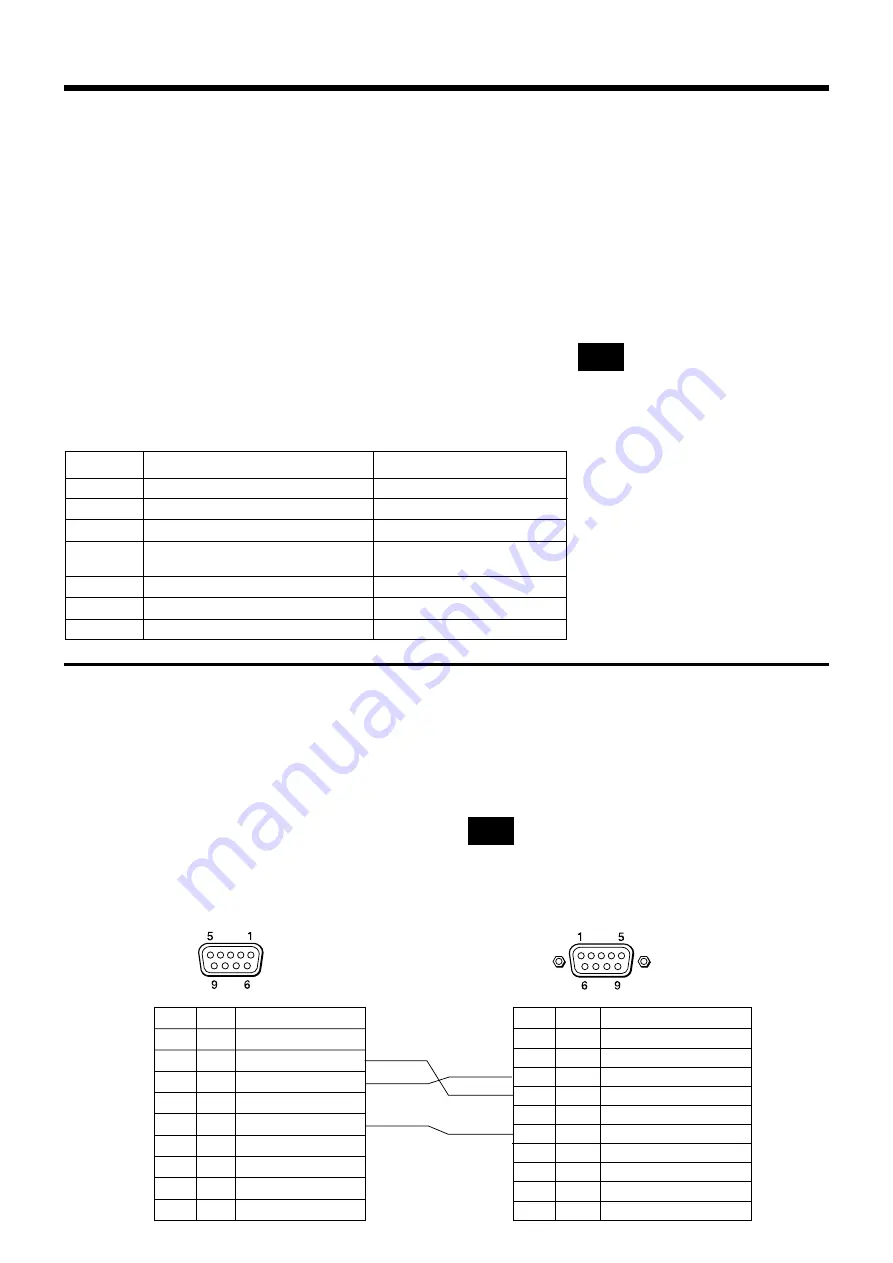
7
Flashing button Name of Model Name of Terminal to be Connected
INPUT 1 Sony VPL-FX51/50, VPL-PX11
INPUT 2 Sony VPL-PX32/31/21
INPUT 3 Sony PFM-42B2/42B1
INPUT 4 SANYO Electric Co., Ltd. PLC-XF10
etc.
INPUT 5 Sony VPL-PX40
INPUT 6 Sony PFM-50C1/32C1
INPUT 10 No control
INPUT A Terminal
INPUT A Terminal
INPUT 1 Terminal
VIDEO IN-1 Terminal,
COMPUTER IN-1 Terminal
INPUT D Terminal
INPUT 1 Terminal
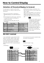
To control a projector or display to connect with, this
apparatus shall be set according to its model in the follow-
ing procedures.
1. While pressing both OUTPUT 1 and OUTPUT 2/
MONITOR OFF buttons, turn on the POWER button to
ON.
2. Projector/Display Selection Mode appears, and the button
to correspond to the actually set model flashes for
confirmation of the setting.
For setting of applicable models, please refer to the
following table.
3. While the button is flashing, press the button to corre-
spond to the model to which you want to change, and the
setting is changed.
When "settings of both OUTPUT 1 and 2 systems are not
changed or any operation was done for 5 seconds", the
setting is stored and the apparatus enters the ordinary
operation. This setting is stored even if power is turned
OFF.
• When OUTPUT 2 MODE switch is set
to MONITOR, projector or display is
not controlled from the RS-232C
OUTPUT 2 CONTROL terminal.
Therefore, in the Projector/Display
Selection mode, OUTPUT 2 LED goes
off and the selection is impossible.
• Other models than those listed in the
left table may be also applicable.
Please contact your local Sony Sales
Office or Dealer.
RS-232C terminal
Connect the CONTROL 1 terminal with the OUTPUT 1
output, and CONTROL 2/REMOTE terminal with the
OUTPUT 2 output of the projector or plasma display.
Linked with the operation of this unit, the projector or
plasma display will turn POWER ON/STANDBY, or
perform the selection of RGB or component input signal
formats.
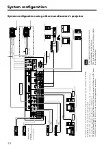
For the connection of a Sony projector and plasma display,
connect them as following diagram.
(9 pin D-sub, male)
(9 pin D-sub, female)
< PVS-R102 side >
< Sony Projector/Display side >
How to Control Display
Selection of Projector/Display to Connect
Use a cable of less than 15 m long.
Note
Note
Note
1 FG Frame GND
2 RD Received Data
3 TD Transmitted Data
4 ER Data terminal Ready
5 SG Signal GND
6 DR Data Set Ready
7 RS Request to Send
8 CS Clear To Send
9 N.C Non Connection
Pin No. Signal Function
1 DCD Data Carrier Detect
2 RX DA Received Data
3 TX DA Transmitted Data
4 DTR Data Terminal Ready
5 GND GND
6 DSR Data Set Ready
7 RTS Request to Send
8 CTS Clear To Send
9 RI Ring Indicator
Pin No. Signal Function
Shell=FG FG GND or cable shield


