000
116
9. Connecting External Devices
Connecting a Remote Control Unit
When an RM-B170 Remote Control Unit,
RCP1001/1501 Remote Control Panel, or other
control unit is connected, some camcorder
functions can be controlled from that unit.
You can use the display on the RM-B170 or a video
monitor connected to the MONITOR connector
of the remote control unit to perform camcorder
menu operations and monitor the camcorder
picture.
Connecting a Remote Control Unit
Using the remote control cable, connect between
the REMOTE connector (8-pin) of the camcorder
and the camera connector of the remote control
unit.
When you turn on the camcorder after making the
connection, the camcorder enters remote control
mode, enabling menu operations and shooting
operations.
[Notes]
ˎ
ˎ
Remote control operation is not supported if USB
connection to the camcorder is enabled.
ˎ
ˎ
If a USB connection to the camcorder is enabled during
remote control, remote control mode is released.
ˎ
ˎ
Do not connect or disconnect the remote control unit
when the camcorder is on.
ˎ
ˎ
A remote control cable is not supplied with the RCP-
1001/1501 Remote Control Unit.
The following switches of the camcorder are
disabled when a remote control unit is connected.
ˎ
ˎ
GAIN switch
ˎ
ˎ
WHITE BAL switch
ˎ
ˎ
AUTO W/B BAL switch
ˎ
ˎ
SHUTTER switch
ˎ
ˎ
OUTPUT/DCC switch
ˎ
ˎ
ASSIGN. 1/3 switches, ASSIGNABLE 4/5 switches,
and the ONLINE button to which the Turbo Gain
or ATW function has been assigned
Releasing Remote Control Mode
Turn off the camcorder and disconnect the remote
control unit.
The switch settings on the camcorder become
enabled.
Connecting a Monitor to an RM-B170
The MONITOR connector (BNC type) of the RM-
B170 outputs the same signal as the output from
the VIDEO OUT connector.
To connect a monitor to the MONITOR connector
on the RM-B170, use the black cable supplied with
the RM-B170.
Image Quality Adjustment when an
RM-B170 is Connected
When the RM-B170 is connected, the parameters
for camera image quality adjustment items (paint
data) are set to the parameters that were specified
the last time that the RM-B170 was connected.
Function of Recording Start/Stop
Buttons when an RM-B170 is
Connected
Set the function of the buttons using Maintenance
>Camera Config >RM Rec Start in the setup menu.
The functions of the buttons for the RM Rec Start
settings are given below.
Button
RM Rec Start setting
RM
Camera
PARA
Camcorder REC
START button
Disabled Enabled
Enabled
Lens VTR button
Disabled Enabled
Enabled
ASSIGN. 1/3
switches,
ASSIGNABLE 4/5
switches, and
ONLINE button
assigned with
recording start/
stop function
Disabled Enabled
Enabled
RM-B170 VTR
button
Enabled
Disabled Enabled
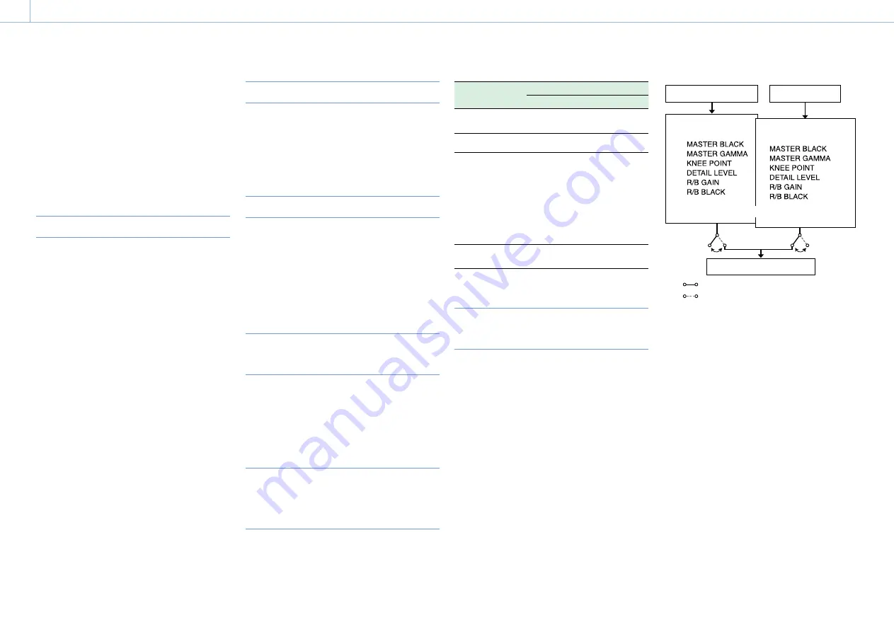
Data Structure of Image Quality
Adjustment Data
The non-volatile memory of the camcorder used
for storing camera image quality adjustment data
(paint data) consists of the two regions shown
below: a “main data block” that is used when
a remote control unit is not connected, and a
“remote control data block” that is used when a
remote control unit is connected. Paint adjustment
data is automatically selected and output to the
camera section depending on whether or not
a remote control unit, such as the RM-B170, is
connected.
Camcorder setup menu
Main data block
Remote control data
block
Camera unit hardware
RM-B170 connected
RM-B170 not connected
RM-B170
Camcorder non-volatile memory
When a remote control unit is connected, the
“remote control data block” is selected as the
current paint data block, and the paint adjustment
parameters that were in effect the last time the
remote control unit was used are loaded.
However, when the settings of absolute value
controls
1)
and absolute value switches
2)
are set
on the remote control unit, the settings on the
remote control unit override the settings on the
camcorder.
When the remote control unit is disconnected
from the camcorder, the “main data block” is re-
enabled, and the camcorder returns to the settings
that were in effect before the remote control unit
was connected.
1) Absolute value controls: Data corresponding to the
angular position of the control is output. Controls for
which data corresponding to the amount of rotation is
output are called relative value controls.
2) Absolute value switches: Switches (or knobs), such
as toggle switches or slide switches (except most
momentary switches) whose positions must coincide with
their functions are called absolute value switches.
When Maintenance >Camera Config >RM
Common Memory in the setup menu is set to
[On], you can use settings of the paint adjustment


