6-16E
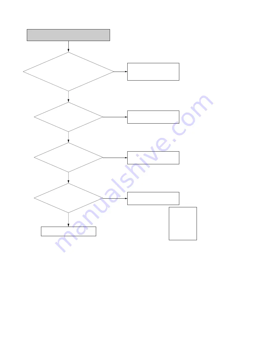
DTV mode Error
Is the 1pin of T_U221-3.3V ,
the 3pin of T_U231-1.5V ok?
Check the T_A3.3V line and
T_D1.5V line.
Yes
Is the 5pin,6pin of
T_U441 , the 5pin,6pin of T_U461
ok?
Check the I2C signal line from
MICOM to T_U441 and T_U461.
No
No
Yes
Is the DDR Clock
T_R510, T_R511 ok?
Change the T_U1
Yes
Is the DATA
(T_RP402, T_RP403) and the
DCLK(T_R401) from the
TUNER (E1) ok?
Check the voltage and the
DATA,DCLK from E1.
No
No
Yes
Change the DJACK PCB
# Nomal level
: 1pin - 5V
3pin - 5V
5pin - 33V
12pin - 3.3V
15pin - 1.2V
Summary of Contents for RDR-GX255
Page 36: ...1 26E MEMO ...
Page 40: ...2 4E MEMO ...
Page 42: ...3 4E MEMO ...
Page 44: ...4 1 DVD Main PCB 4 4 4 3 COMPONENT SIDE ...
Page 45: ...4 6 4 5 CONDUCTOR SIDE ...
Page 46: ...4 8 4 7 4 2 Front Main PCB COMPONENT SIDE ...
Page 47: ...4 10 4 9 CONDUCTOR SIDE ...
Page 48: ...4 12E 4 11 4 3 Function Timer PCB COMPONENT SIDE CONDUCTOR SIDE ...
Page 50: ...5 4 5 3 5 1 S M P S Front Main PCB ...
Page 51: ...5 6 5 5 5 2 Power Front Main PCB ...
Page 52: ...5 8 5 7 5 3 Logic Front Main PCB ...
Page 53: ...5 10 5 9 5 4 Function Jack VCR Front Main PCB ...
Page 54: ...5 12 5 11 5 5 MPEG Decoder DVD Main PCB ...
Page 55: ...5 14 5 13 5 6 A V Decoder DVD Main PCB ...
Page 56: ...5 16 5 15 5 7 In Out DVD Main PCB ...
Page 57: ...5 18 5 17 5 8 ATSC DVD Main PCB ...
Page 58: ...5 20 5 19 5 9 Tuner DVD Main PCB ...
Page 59: ...5 22 5 21 5 10 DV HDMI DVD Main PCB ...
Page 60: ...5 24E 5 23 5 11 Front Panel Function Timer PCB ...
Page 77: ...7 1 RDR GXD455 7 REPAIR PARTS LIST 7 1 Exploded Views 7 2 7 2 Electrical Parts List 7 3 ...


