background image

6-5

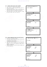
6-9.

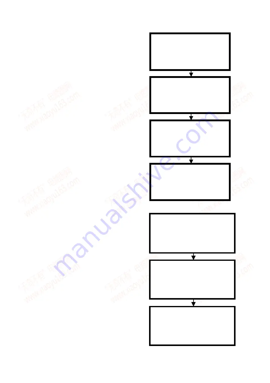
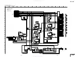
Device All Check. Screen Transition

1.

Select the item “ALL CHECK” from the menu.

2.

Device check is executed automatically starting from No. 1
one device after another.

3.

When all devices are checked, number of OK/NG items and
names of the NG devices are displayed as the RESULT.

4.

When the ENTER key of the remote commander is pressed,
the monitor display returns to the menu screen.

<< DEVICE TEST MENU 1/2 >>

0) ALL CHECK

<< VIDEO ENC >>
REGISTER                  OK

<< OK >>

<< IP CONV >>
REGISTER                   NG

<< NG >>

<< RESULT >>
 -- OK [27] -- NG [1] --
 NG[ IP CONV                    ]

6-10. Device Individual Check. Screen Transition

1.

Select the TL750 item from the menu.

2.

The register read/write that is the first item of the check is
executed and its result is displayed.

3.

The SDRAM check that is the second item of the check is
executed and its result is displayed.

4.

When check results of all items are OK, the message OK is
displayed. If any one of the check items is found NG, the
message NG is displayed.

5.

When the ENTER key is pressed, the monitor display moves
the to the menu screen.

<< DEVICE TEST MENU 1/2 >>

· · · ·

3) TL750

· · · ·

<< TL750 >>
REGISTER                  OK
SDRAM                     OK

<< OK >>

<< TL750 >>
REGISTER                   OK
SDRAM                      NG

<< NG >>

www. xiaoyu163. com

QQ 376315150

9

9

2

8

9

4

2

9

8

TEL 13942296513

9

9

2

8

9

4

2

9

8

0

5

1

5

1

3

6

7

3

Q

Q

TEL  13942296513  QQ  376315150  892498299 

TEL  13942296513  QQ  376315150  892498299 

http://www.xiaoyu163.com

http://www.xiaoyu163.com

Summary of Contents for RDR-GX7

Page 1: ...verted to 48 kHz sampling frequency Inputs and outputs LINE OUT 1 2 AUDIO Phono jack Output level 2 Vrms Load impedance 10 kilohms VIDEO Phono jack Output level 1 0 Vp p S VIDEO 4 pin mini DIN Output level Y 1 0 Vp p C 0 286 Vp p NTSC LINE IN 1 2 3 AUDIO Phono jack Input level 2 Vrms Input impedance more than 22 kilohms VIDEO Phono jack Input level 1 0 Vp p S VIDEO 4 pin mini DIN Input level Y 1 0...

Page 2: ...nted with the lead free mark due to their particular size LEAD FREE MARK Unleaded solder has the following characteristics Unleaded solder melts at a temperature about 40 C higher than ordinary solder Ordinary soldering irons can be used but the iron tip has to be applied to the solder joint for a slightly longer time Soldering irons using a temperature regulator should be set to about 350 C Cauti...

Page 3: ...dited Contents Copy Dubbing 1 21 Recording From Equipment Connected to the LINE IN Jacks 1 21 Settings and Adjustments 1 22 About the Setup Display Structure 1 22 Using the Setup Displays 1 22 Settings Basic Settings 1 22 Video Settings 1 23 Audio Settings 1 23 Features Settings 1 23 Options Settings 1 24 Easy Setup Resetting the Recorder 1 24 Additional Information 1 24 Troubleshooting 1 24 Self ...

Page 4: ...n 6 5 6 11 Path Individual Check Pasted Screen Check Screen Transition 6 6 6 12 Path Individual Check Data Check Confirmation Screen Transition 6 6 7 ADJUSTMENT 7 1 VIDEO SYSTEM ADJUSTMENT 7 1 1 Video Level Adjustment RD 045 Board 7 1 2 Component Video Output Level Adjustment RD 045 board 7 1 3 S Video Output S Y Level Check 7 1 4 S Video Output S C Check 7 1 5 Component Video Output Y Check 7 2 6...

Page 5: ...Note2 If you close the tray with a CD disc inserted in it the CD can be ejected However if you close the tray while it is empty there can be a case that ejection of the tray becomes impossible Note3 Even if you replace the DVD drive unit while the tray remains under the state as described above the situation cannot be improved 2 If the tray cannot be ejected while the disc is not inserted Execute ...

Page 6: ...u163 com QQ376315150 9 9 2 8 9 4 2 9 8 TEL 13942296513 9 9 2 8 9 4 2 9 8 0 5 1 5 1 3 6 7 3 Q Q TEL 13942296513 QQ 376315150 892498299 TEL 13942296513 QQ 376315150 892498299 http www xiaoyu163 com http www xiaoyu163 com ...
Page 7: ...r copies the entire contents of a DV Digital8 format tape to a DVD RW in VR mode whereupon the contents are automatically divided into chapters The chapters are displayed as scenes in a scene list where you can instantly delete or rearrange the scenes at will The recorder remembers which scenes you selected and saves this information as a program You can call up a program at any time and make addi...

Page 8: ...the TV screen T ONE TOUCH DUB button 78 Records the contents of a DV Digital8 format tape with a single touch of the button U REC MODE button 38 Selects the recording mode V previous next buttons 52 Goes to the next title chapter track or goes back to the previous title chapter track W CHANNEL buttons 38 Selects the channel or input line X PROGRESSIVE button 51 Switches the output signal progressi...

Page 9: ...to call the CATV system installer s attention to Article 820 40 of the NEC that provides guidelines for proper grounding and in particular specifies that the cable ground shall be connected to the grounding system of the building as close to the point of cable entry as practical Notes If your antenna is a flat cable 300 ohm twin lead cable use an external antenna connector not supplied to connect ...

Page 10: ...receiver with a digital input jack having a Dolby Digital or DTS 2 decoder and 6 speakers Surround effects Dolby Digital 5 1ch DTS 5 1ch A B C D continued 20 Step 4 Connecting the Audio Cords Connecting to your TV This connection will use your TV s speakers for sound The yellow plug is used for video signals page 18 z Hint When connecting to a monaural TV use a stereo mono conversion cord not supp...

Page 11: ...et 3 5 Searching for receivable channels Please wait Ch45 EASY SETUP TV Type 4 5 Select your TV screen type 16 9 4 3 Letter Box 4 3 Pan Scan continued 24 Step 7 Easy Setup j Press ENTER The Setup Display for selecting the type of jack used to connect to your amplifier receiver appears k Press M m to select the type of jack if any you are using to connect to an amplifier receiver then press ENTER C...

Page 12: ...Setting Up the Remote If you have a Sony DVD player or more than one Sony DVD recorder If the supplied remote interferes with your other Sony DVD recorder or player set the command mode number for this recorder and the supplied remote to one that differs from the other Sony DVD recorder or player The default command mode setting for this recorder and the supplied remote is DVD3 a Press SYSTEM MENU...

Page 13: ...le List Original or Title List Playlist menu appears and displays the Original or Playlist titles on the disc The PLAYLIST indicator lights up on the front panel display when the Title List Playlist menu is selected To switch the Title List menu for a DVD RW VR mode The recorder displays either the Original or Playlist Title List Follow the steps below 1 Press TITLE LIST The Title List menu appear...

Page 14: ...ontents will be erased after reformatting Recording mode While the recorder is stopped you can select one of six recording modes by pressing REC MODE repeatedly for the desired recording time and picture quality The picture quality generally improves as the recording time decreases Notes The recording times are an estimate and actual times may differ Situations below may cause slight inaccuracies ...

Page 15: ...ecording information appears 1 Disc type format 2 Recording status 3 Recording mode 4 Recording time b Press DISPLAY to turn off the display Creating chapters in a title The recorder can automatically divide a recording a title into chapters by inserting chapter marks at 6 or 15 minute intervals during recording Select the interval 6Min default or 15Min in Auto Chapter of Features Setup page 97 z ...

Page 16: ...at 10 00AM 10 30AM 25ch SP OK Cancel Mon Sat 10 00AM 10 30AM 25ch SP Wed 10 29 9 00AM 10 15AM 3ch SLP Check Overlap These timer settings overlap Change priority Close 7 00 7 00 9 00 10 30 A 9 00 11 00 A B C C 10 30 B will be cut off Actual recording 7 00 9 00 11 00 A B C 7 00 9 00 10 00 A B Sat 10 25 8 30PM 9 30PM 4ch Mon Sat 10 00AM 10 30AM 25ch Wed 10 29 9 00AM 10 15AM 3ch Thu 10 30 4 00PM 5 00P...

Page 17: ...panel The recorder automatically turns off and stands by for Synchro Recording The recorder automatically starts recording when it receives an input signal from the connected equipment The recorder stops recording when the connected equipment turns off To stop recording Press x REC STOP To cancel Synchro Rec Press SYNCHRO REC or turn on the recorder before the Synchro Recording Starts The SYNCHRO ...

Page 18: ...our screen when output in PROGRESSIVE mode 60 frames per second the progressive video signal needs to be converted to match the type of DVD software that you are watching The title recorded on this recorder is Video based software If you want to set the conversion mode for Video based software regardless of the software type set Progressive Mode in Video Setup to Video page 95 Notes When you play ...

Page 19: ... or track Also you can check the disc name recorded on the disc Press DISPLAY repeatedly Each time you press the button the display changes as follows The displays differ depending on the disc type or playing status Display 1 Example When playing a DVD VIDEO 1 Title track number name 2 Available disc functions angle audio subtitle etc 3 The current selected function or audio setting appears only t...

Page 20: ...he disc You cannot change the angles when playing a disc recorded on this recorder L Front speaker left R Front speaker right Virtual speaker L R ANGLE Angle 1 3 60 Displaying the Subtitles Displaying the Subtitles If subtitles are recorded on a disc you can change the subtitle language or turn the subtitles on and off whenever you want during playback Press SUBTITLE repeatedly during playback to ...

Page 21: ... enter up to 64 characters for a name The title name will be displayed in the Title List menu a Press TITLE LIST The Title List menu appears If you are using a DVD RW VR mode press TOOLS and select either Original or Playlist from the TOOLS menu to change the Title List if necessary b Press M m to select the title then press ENTER The sub menu appears c Press M m to select Title Name then press EN...

Page 22: ... ENTER A check mark appears in the check box next to the selected title To clear the check mark press ENTER again To select all of the titles select Select All e Repeat step 4 when adding more titles To go to the next page press m To clear all the check marks select Reset All f Press to select OK then press ENTER The list of selected titles appears To add another title select Add Title g Press M m...

Page 23: ...Info then press ENTER The Disc Information display appears Example When the inserted disc is a DVD RW VR mode c Press M m to select Disc Name then press ENTER The display for entering a disc name appears d Enter a name by following the explanation on page 34 The Disc Information display appears with the new disc name e Press RETURN to turn off the display Note The disc name will not appear when th...

Page 24: ...TER Stereo1 default Mix both stereo 1 and stereo 2 Stereo2 You are ready to start recording z Hints You can adjust the settings for the recording picture before recording See Adjusting the Recording Picture Quality and Size page 46 If you plan to re edit the program page 77 insert a DVD RW and format it in VR mode Notes You cannot connect more than two pieces of digital video equipment to the reco...

Page 25: ...scene to the Scene List menu To preview the scene select Preview To reset either the IN or OUT point select Change IN or Change OUT Repeat from step 5 h Press M m to select OK then press ENTER A new Scene List menu appears with the selected scene i Press M m to select Add and press ENTER Then repeat steps 5 to 9 to select all the scenes you want to include You can add up to 50 scenes to a title To...

Page 26: ...VR mode that corresponds to the program in the DV D8 Edit List m m m The recorder will fast forward and rewind the tape automatically and record the scenes to a disc of your choice a Follow steps 1 to 4 of Preparing for recording using the DV IN jack page 75 then press SYSTEM MENU Be sure to use the original DV Digital8 format tape and the DVD RW VR mode that corresponds to the program in the DV D...

Page 27: ...order for a One Touch Dub recording to be added to the DV D8 Edit List Add to Edit List in Features Setup must be set to On page 98 Copy dubbing may not work if you have edited sections that do not contain any recorded material This function may not work with certain digital video cameras In this case follow the instructions of Recording From Equipment Connected to the LINE IN Jacks page 88 DV D8 ...

Page 28: ...reset correctly or completely during Auto Preset or Easy Setup Set the correct tuner system manually by the steps below 1 Follow steps 1 to 3 of Using the Setup Displays page 91 to select Settings in the Setup Display 2 Press M m to select Tuner Preset then press ENTER 3 Press M m to select Antenna Cable then press ENTER To preset cable TV channels Press M m to select Cable then press ENTER To pre...

Page 29: ...Checking the audio signal format page 58 This function affects the output of the following jacks LINE OUT AUDIO L R 1 2 jacks DIGITAL OUT OPTICAL or COAXIAL jack when Dolby Digital is set to D PCM page 96 Digital Out Selects if audio signals are output via the DIGITAL OUT OPTICAL or COAXIAL jacks To set the digital output signal The following setup items switch the method of outputting audio signa...

Page 30: ...he default Command Mode conflicts with other DVD equipment DVD3 The default Command Mode of the recorder Settings Video Audio Features Options Easy Setup Format Disc Dimmer Auto Display Command Mode Factory Setup Selectable Bright On DVD3 SETUP 100 Easy Setup Resetting the Recorder Easy Setup Resetting the Recorder Select this to restart Easy Setup mode for basic setup Select Easy Setup in the Set...

Page 31: ...e AC power cord from the AC outlet and connect it again The program contains copy protection signals that restricts copying The timer setting overlapped with another setting that was set later or has priority page 43 Recording does not stop immediately after you press the x REC STOP button It will take a few seconds for the recorder to input disc data before recording can stop Recording does not s...

Page 32: ...D The data capacity of a double layer and single sided DVD is 8 5 GB a single layer and double sided DVD is 9 4 GB and double layer and double sided DVD is 17GB The picture data uses the MPEG 2 format one of the worldwide standards of digital compression technology The picture data is compressed to about 1 40 average of its original size The DVD also uses a variable rate coding technology that cha...

Page 33: ...age 2 5 Shaft R Page 2 5 DVD drive Page 2 8 FL 130 board Page 2 7 FR 195 board Page 2 7 AV 071 board Page 2 9 RD 045 board Page 2 6 Tray cover assembly Page 2 4 Top case Page 2 2 Set www xiaoyu163 com QQ376315150 9 9 2 8 9 4 2 9 8 TEL 13942296513 9 9 2 8 9 4 2 9 8 0 5 1 5 1 3 6 7 3 Q Q TEL 13942296513 QQ 376315150 892498299 TEL 13942296513 QQ 376315150 892498299 http www xiaoyu163 com http www xia...

Page 34: ... 10 6 Remove the power block in the direction of the arrow 5 Five tapping screws BV sumitite B3 8 1 Connector CN4 14P 2 From DVD drive CN1 4P 3 Connector CN3 13P 7 P C board spacer A A B C B C www xiaoyu163 com QQ376315150 9 9 2 8 9 4 2 9 8 TEL 13942296513 9 9 2 8 9 4 2 9 8 0 5 1 5 1 3 6 7 3 Q Q TEL 13942296513 QQ 376315150 892498299 TEL 13942296513 QQ 376315150 892498299 http www xiaoyu163 com ht...

Page 35: ...tite B3 10 5 Tapping screw BV sumitite B3 10 3 Screw B 3 3 6 Cap rear 2 Seven tapping screws BV sumitite B3 10 7 Rear panel 1 Connector CN102 3P www xiaoyu163 com QQ376315150 9 9 2 8 9 4 2 9 8 TEL 13942296513 9 9 2 8 9 4 2 9 8 0 5 1 5 1 3 6 7 3 Q Q TEL 13942296513 QQ 376315150 892498299 TEL 13942296513 QQ 376315150 892498299 http www xiaoyu163 com http www xiaoyu163 com ...
Page 36: ...y 3 Two claws 3 Front panel section 1 Two tapping screws BV sumitite B3 8 2 Five claws www xiaoyu163 com QQ376315150 9 9 2 8 9 4 2 9 8 TEL 13942296513 9 9 2 8 9 4 2 9 8 0 5 1 5 1 3 6 7 3 Q Q TEL 13942296513 QQ 376315150 892498299 TEL 13942296513 QQ 376315150 892498299 http www xiaoyu163 com http www xiaoyu163 com ...

Page 37: ...ow Ground door plate Aluminum door Door base 5 Shaft R 2 Two shaft C 1 Shaft L 3 Tapping bind screw B 2 6 8 4 Damper www xiaoyu163 com QQ376315150 9 9 2 8 9 4 2 9 8 TEL 13942296513 9 9 2 8 9 4 2 9 8 0 5 1 5 1 3 6 7 3 Q Q TEL 13942296513 QQ 376315150 892498299 TEL 13942296513 QQ 376315150 892498299 http www xiaoyu163 com http www xiaoyu163 com ...

Page 38: ...002 CN1901 47P 2 Flexible flat cable FRA 003 CN1902 40P 1 Flexible flat cable FRD 002 CN1103 40P qa RD 045 board 0 Bracket RD 4 Harness RD FL CN2001 6P 5 Harness RD PS CN1701 14P www xiaoyu163 com QQ376315150 9 9 2 8 9 4 2 9 8 TEL 13942296513 9 9 2 8 9 4 2 9 8 0 5 1 5 1 3 6 7 3 Q Q TEL 13942296513 QQ 376315150 892498299 TEL 13942296513 QQ 376315150 892498299 http www xiaoyu163 com http www xiaoyu1...

Page 39: ...95 BOARD 3 Two tapping screws BV sumitite B3 8 5 Cursor 6 FR 195 board 4 Three claws 1 Flexible flat cable FFF 018 CN102 10P 2 Flexible flat cable FAR 003 CN101 19P www xiaoyu163 com QQ376315150 9 9 2 8 9 4 2 9 8 TEL 13942296513 9 9 2 8 9 4 2 9 8 0 5 1 5 1 3 6 7 3 Q Q TEL 13942296513 QQ 376315150 892498299 TEL 13942296513 QQ 376315150 892498299 http www xiaoyu163 com http www xiaoyu163 com ...

Page 40: ...t right 1 Harness DR PS CN1 4P 4 Remove the DVD section in the direction of the arrow qs DVD drive 7 Flexible flat cable FRD 002 CN1802 40P 5 Harness DR PS 4P www xiaoyu163 com QQ376315150 9 9 2 8 9 4 2 9 8 TEL 13942296513 9 9 2 8 9 4 2 9 8 0 5 1 5 1 3 6 7 3 Q Q TEL 13942296513 QQ 376315150 892498299 TEL 13942296513 QQ 376315150 892498299 http www xiaoyu163 com http www xiaoyu163 com ...

Page 41: ...071 board 8 Two P C board spacer 7 Flexible flat cable FAE 012 CN502 27P 6 Flexible flat cable FRA 003 CN202 39P 5 AV 071 boar www xiaoyu163 com QQ376315150 9 9 2 8 9 4 2 9 8 TEL 13942296513 9 9 2 8 9 4 2 9 8 0 5 1 5 1 3 6 7 3 Q Q TEL 13942296513 QQ 376315150 892498299 TEL 13942296513 QQ 376315150 892498299 http www xiaoyu163 com http www xiaoyu163 com ...

Page 42: ...oard FL 130 board CN 177 board Power block www xiaoyu163 com QQ376315150 9 9 2 8 9 4 2 9 8 TEL 13942296513 9 9 2 8 9 4 2 9 8 0 5 1 5 1 3 6 7 3 Q Q TEL 13942296513 QQ 376315150 892498299 TEL 13942296513 QQ 376315150 892498299 http www xiaoyu163 com http www xiaoyu163 com ...

Page 43: ...UFF Q712 UVI CV VSYNC H DET SEP V REC C REC Y CVBSS GTUD DATA GTUD LRCK GTUD BCK AAD DATA AAD LRCK AAD BCK CEVA SDO CEVA SDO 2ch D A CONV IC301 3 1 3 2 1 5 6 7 IC303 IC304 5 7 RD 045 1 2 BOARD BUFF Q809 V BUFF Q810 C BUFF Q811 Y BUFF Q812 Y G BUFF Q813 CB B BUFF Q814 CR R Y C PROCESSOR IC802 COMPONENT OUT V G C Y G G C Y G L R J805 J801 0UT R1 0UT L1 0UT L2 0UT R2 Cr Cb Y UVI CV VSYNC H DET SEP V ...

Page 44: ...101 107 KEY1 IC101 FUNCTION KEY S108 110 KEY2 FUNCTION KEY S111 116 KEY3 FUNCTION KEY S117 122 KEY5 REMOTE CONTROL RECIVER SIRCS DIMMER P CONT Q102 5V REG Q101 5V LED 5V P FAIL UNSW 6V P FAIL RESET DET IC604 RESET D602 VDD D603 5V IC603 BUZZER BZ601 UNSW18V UNSW18V SW3 3V 5V REG IC102 SW5V SW3 3V UNSW6V 5V REG IC106 UNSW5V UNSW13V 12V REG IC105 UNSW12V UNSW13V 10V REG SW 10V UNSW 10V Q100 UNSW 10V...

Page 45: ...ASP IDE_D15 IDE_INT GND IDE_DACK IDE_HD16 IDE_D13 IDE_A4 CS0 IDE_D4 IDE_D11 GND IDE_D14 N C IDE_D1 N C IDE_D8 GND IDE_RST IDE_A0 GND GND N C IDE_W IDE_D5 IDE_A2 IDE_D10 GND IDE_D0 IDE_A0 N C IDE_D0 IDE_D2 IDE_D14 IDE_IORDY GND IDE_D6 GND GND IDE_A4 CS0 IDE_D7 N C IDE_R IDE_RST IDE_D9 DASP IDE_HD16 N C GND IDE_D10 IDE_D8 IDE_A4 CS1 GND IDE_A1 IDE_D4 GND GND IDE_A2 IDE_D5 IDE_DACK IDE_D11 IDE_D1 IDE...

Page 46: ...oted 2 non flammable resistor 5 fusible resistor C panel designation f internal component C adjustment for repair U B Line V B Line Circled numbers refer to waveforms Voltages are dc between measurement point Readings are taken with a color bar signals on DVD reference disc Readings are taken with a digital multimeter DC 10MW Voltage variations may be noted due to normal production toler ances 4 2...

Page 47: ...R481 PQ070XZ01ZP IC402 1 VCC 2 CTL 3 OUT 4 NC 5 GND 6 OUT 1k R401 0 22u B C404 0 1u B C409 16V 47u C412 0 5 100k R402 0 5 5600 R403 0 5 33k R409 2SB709A QRS TX Q413 2SD601A QRS TX Q420 1k R428 1500 R429 100 R432 820 R430 R433 XX R434 XX 0 R415 TK11850L 1TL IC406 VIN 1 IS 2 EXT 3 VO 4 VFB 5 GND 6 CX 7 EN 8 1 R440 100uH L412 RB501V 40TE 17 D411 JL430 50V 4 7u C436 47uH L411 68p C469 0 5 5600 R484 0 ...

Page 48: ...4 50V 2 2u C763 R721 0 2SA1162 YG TE85L Q710 16V 47u C746 4700 R728 0 R726 2SB1561T100Q Q708 1k R723 10k R717 UN2212 TX Q706 4700 R718 4700 R716 1SS355TE 17 D705 1SS355TE 17 D706 16V 47u C735 UNSW5V SYNCPOW XX IC704 1 2 3 4 5 6 XX IC702 1 2 3 4 5 6 XX C734 XX C723 XX C732 XX C733 XX C718 XX C719 XX C737 XX Q703 XX Q701 XX R713 XX R708 XX R709 XX R704 16V XX C712 L1VID XX R710 XX R714 L3VID XX Q704...

Page 49: ... 2 3 4 5 6 7 8 9 10 11 12 13 14 15 16 17 18 19 20 21 22 23 24 25 26 27 28 29 30 31 32 33 34 35 36 37 38 39 40 CN1203 1 2 3 4 5 XVMUTE XAVRST ONDO JL305 1 A PL1512L1 PL1512L1 SPDIFO SPDIFO DGND AGND IT_XAWAKE DGND AI_BCK DGND AGND IT_SIN AGND SHSTATUS1 AGND AI_SDT IT_SCLK DGND EPGGND AAD_XRST FC43 IT_REQ B31 FY33 XITFLMRST CVBSS SHSTATUS0 256FS DGND SPDIFI FSW AGND EPGVIDEO AAD_XSCS IT_XRST AGND AG...

Page 50: ...0 XX R857 XX R858 68 R843 68 R850 68 R842 68 R849 XX R871 XX R870 XX R873 XX R872 68 R844 68 R845 HZM6 8ZWA1TL D803 HZM6 8ZWA1TL D809 XX R881 XX R882 XX R889 XX R890 75 R869 75 R855 75 R865 75 R866 75 R867 75 R868 68 R846 68 R847 68 R848 JL807 XX R876 XX R875 XX R874 XX D804 XX D805 XX D806 XX R859 XX R860 XX R861 XX R852 XX R853 XX R854 JL832 JL833 JL834 JL801 JL835 JL836 JL837 JL838 XX R877 XX R...

Page 51: ...IN4 4 WTMO 5 LIN3 6 ZELMN 7 LIN2 8 FS 9 LIN1 10 LOPIN 11 LOUT 12 IPGAL 13 IPGAR 14 ROUT 15 ROPIN 16 AVDD 17 AVSS 18 VCOM 19 DVSS 20 DVDD 21 SDTO 22 BICK 23 LRCK 24 MLCK 25 PDN 26 ALC 27 SMUTE 28 SEL0 29 SEL1 30 SEL2 31 CDTI SDA 32 CCLK SCL 33 CNS CAD1 34 CTRL 35 M S 36 RIN1 37 TEST5 38 RIN2 39 TEST6 40 RIN3 41 TEST7 42 RIN4 43 TEST8 44 RIN5 GND XX R231 EUAUINL1 100 R277 XAVRST 22k R278 22k R279 22...

Page 52: ...C301 220k R301 XX C303 100k R308 2SD601A QRS TX Q302 5600 R309 EC10DA40 TE12 D302 XX C305 XX C304 10k R307 2SB1561T100Q Q303 XX C311 63V 47u C310 16V C315 47u XX C312 XX R304 XX R305 XX R306 XX R314 22 R310 100 R311 XX R312 2SC2712 YG TE85L Q315 2SC2712 YG TE85L Q316 2SB709A QRS TX Q308 Q310 2SD1938 F T TX SO Q312 2SD1938 F T TX SO 2SA1162 YG TE85L Q317 Q311 2SD1938 F T TX SO Q313 2SD1938 F T TX S...

Page 53: ...C1118 1k R1119 2SB709A QRS TX Q1104 1k R1127 47k R1124 50V 10u C1120 1k R1120 220p C1119 0 1u B C1121 47k R1125 100k R1130 JL1110 JL1111 X1101 3 579545MHZ UVICSIN UVICSOUT 1 A PAR SER OSC2 TEST PLLTD BUSY VSS3 OSC1 EXT RESET AD5 AD3 AD4 AD6 AD1 SDTA AD2 SWIN AD7 AD0 SCLK VSS2 VSS1 VDD1 PLLTA XFC SYNC VDATA VDD3 VDD3 SDI AS SDO RW CS SCK E VSS3 VDD2 CSA DIGITAL Q1101 1105 DATA SYNC SEPA B B B B 9 9...

Page 54: ...DI5 ITREQ5 CEVISDO5 TU_AFT TU_AMUTE XAWAKE5 CEVISCK5 UVICCS TU_G_MAX TU_S B_D DVDEXT VYL3 TUDVD XRGBSEL CDINSEL MUON_DET XP_MUTE HDET JUST_CLK TU_AUTOP L1SEL YCSEPON VSYNC XAWAKE5 STATUS1 UVICBSY RESET5V UVICCS XP_MUTE INSEL_1 INSEL_2 L1SEL YCSEPON SYNCPOW HDET VSYNC WIDE DSEL VYL1 AVLINK RELAY TU_SAP_D TU_AFT TU_VDET JUST_CLK TU_AMUTE TU_S B_D TU_G_MAX TU_AUTOP TU_M SAP TU_M SAP FAN_ONOFF TU_VDET...

Page 55: ...SC5053T100Q Q609 2SC5053T100Q Q610 UN2211 TX Q606 1SS355TE 17 D608 VFL F F BS_DET SW5V SW12V UNSW6V UNSW12V UNSW18V GND UNSW5V SW5V GND SW3 3V GND GND UNSW6V UNSW 10V SW12V SW5V SW3 3V GND GND SW3 3V GND GND UNSW12V UNSW6V SW3 3V SW 10V GND GND SW5V GND UNSW6V UNSW5V Q607_5V AC_CONT FAN_ONOFF FAN_SPEED FAN_DET FL_PCONT GND SW5V SW3 3V GND 1 A AC_CONT BS_D_DET FAN_ONOFF FAN_SPEED FAD_DET UNSW5V SW5...

Page 56: ...7 R344 R346 R368 R660 R662 R664 R666 JL436 J801 Q716 R765 PS401 C343 R114 R116 R119 R504 R505 R506 JR014 C344 PS101 PS102 CN1201 CN1202 FL803 J805 D611 C806 C807 C808 C814 C815 C817 C819 CN802 Q802 Q801 Q817 Q818 C803 C811 C812 C816 C818 L801 L802 R801 R808 R835 R836 R839 J601 C639 R128 R1215 R1216 R1227 R1228 R487 C432 LP102 R121 R122 R898 R897 R1206 R1217 C745 R277 CN901 C703 C707 C712 C713 C714...

Page 57: ...1205 JL1206 JL1207 JL1208 R127 R1203 R1204 R1218 R1219 R1226 C432 JL931 LP102 R120 JL1203 JL932 C440 CN901 C701 C702 C704 C705 C706 C708 C709 C710 C711 C712 C713 C715 C716 C717 C718 C719 C720 C721 C722 C724 C728 C731 C732 C733 C734 C735 C736 C737 C738 J802 C746 C748 C751 C753 C760 C761 C762 C763 C764 C765 C766 C767 CN801 D703 D704 D705 D706 D1201 D810 D811 D812 D813 IC702 IC707 JL702 JL827 JL828 J...

Page 58: ...709 C A K D1710 JL1763 JL1764 FB1702 FB1703 C B E Q1703 C B E Q1704 JL1701 R1702 R1703 R1704 R1705 R1706 R1707 R1708 R1709 R1710 R1711 JL1765 JL1766 JL1767 R1715 R1716 C1703 C1704 C1705 C1706 C1708 JL1768 R1723 JL1771 PC00126 JL1770 R1712 R1713 R1714 FB1704 R1718 R1719 D1713 C A K D1711 JL1772 JL1773 JL1774 R1724 JL1775 JL1776 JL1777 JL1778 JL1779 JL1780 JL1781 FL 130 BOARD SIDE A FL 130 BOARD SID...

Page 59: ...COM5 COM6 COM7 COM8 COM9 COM10 COM11 COM12 COM13 COM14 COM15 FLD1_CS FLD_SCLK FLD_RESET COM1 COM2 COM3 COM4 COM5 COM6 COM7 COM8 COM9 COM10 COM11 COM12 COM13 COM14 COM15 FLD_SOUT SEG1 SEG2 SEG3 SEG4 SEG5 SEG6 SEG7 SEG8 SEG9 SEG10 SEG11 SEG12 SEG13 SEG14 SEG15 SEG16 SEG17 SEG18 SEG19 SEG20 SEG21 SEG22 SEG23 SEG24 SEG25 SEG26 SEG27 SEG28 AD2 AD1 SEG1 SEG2 SEG3 SEG4 SEG5 SEG6 SEG7 SEG8 SEG9 SEG10 SEG1...

Page 60: ...R133 R134 R135 R136 R137 R138 R139 R140 R141 R142 R143 R144 R147 R148 R149 R151 R152 JL110 JL111 JL112 JL113 JL114 JL115 JL116 JL145 JL146 JL117 JL118 JL147 JL148 JL149 JL150 JL151 JL152 JL153 JL154 JL155 JL119 JL120 JL121 JL122 JL123 JL124 JL125 JL126 JL127 JL128 JL129 JL130 JL131 JL132 JL133 JL134 JL135 JL136 JL137 JL138 JL139 JL140 JL141 JL142 JL143 JL144 R105 C106 FR 195 BOARD SIDE A FR 195 BO...

Page 61: ...21 JL125 JL123 JL126 JL124 JL128 JL131 JL129 JL127 JL130 JL132 JL135 JL133 JL134 JL136 JL137 JL143 JL138 JL144 JL139 JL141 JL140 JL142 JL151 JL152 JL153 JL154 JL155 JL145 JL146 JL147 JL148 JL149 JL150 1 A R CD VR VIDEO RESERVE PROGRESSIVE FINALIZED DT_REC TIMER SYNCRO_REC CD VR VIDEO FLD_SCLK FLD_CS FLD_RESET R FINALIZED PROGRESSIVE TIMER FLD_RESET FLD_CS FLD_SCLK FLD_SOUT LED_STB DIMMER KEY4 KEY4...

Page 62: ...E_D9 IDE_D5 IDE_D10 IDE_D4 IDE_D11 IDE_D13 IDE_D2 IDE_D12 IDE_D3 IDE_D1 IDE_D14 IDE_D0 IDE_D15 GND GND GND GND GND N C IDE_DREQ IDE_W IDE_R IDE_IORDY N C IDE_DACK IDE_INT IDE_HD16 IDE_A1 N C IDE_A0 IDE_A2 IDE_A4 CS0 IDE_A4 CS1 DASP GND IDE_D7 IDE_A4 CS1 IDE_D11 N C IDE_D1 GND DASP GND IDE_R IDE_D14 IDE_HD16 IDE_A1 IDE_D8 IDE_D4 GND IDE_D3 GND N C N C IDE_D10 IDE_A0 IDE_DREQ IDE_D12 IDE_A2 IDE_RST ...

Page 63: ...control IIC clock output Input of Communication data with SH Output of communication data with SH Output of communication clock with SH LED serial parallel latch output Buzzer output Remote control output FL power supply ON OFF FLD driver data FLD driver clock Reset for FLD driver CS for FLD driver Switching to monaural AVLINK output Write protect Dimmer pulse Reset output to 5V series LSI Reset o...

Page 64: ... sync no sync Mute of C signal Power supply ON during Syncro standby YC sep circuit ON OFF With S PIN input Audio mute Sound multiplex MSP Tuner power supply control With V sync no V sync Output switching Output switching Output switching Speed switching FAN ON OFF AC relay ON OFF With L3 Icont no L3 Icont Abbreviation FAN stopping detection L3 8PIN input Tuner gain Temperature detection Mute ICON...

Page 65: ... main unit to operate the diagnostics 6 1 Device relation diagram Display data for your reference to check the signal path VIDEO ENCODER IP CONVERTER TL750 VIDEO DECODER GT R FBI AV DECODER MSP Data read AV ENCODER Data read DV ADC DAC Data read Audio signal Video signal All parts are mounted on the RD045M T assembly Checking item IC name REF VIDEO ENC IC ADV7300AKST IC2303 IP CONV IC CXD9698R IC2...

Page 66: ...ers uPD72852 CPRM 6 3 Screen Transition in the Service Mode MAIN MENU 1 DEVICE TEST 2 PATH TEST 3 TEST MODE DEVICE TEST MENU 1 2 0 ALL CHECK 1 VIDEO ENC t 2 IPCONV Main menu MENU 2 DEVICE TEST MENU 2 2 1 DV T 2 CPRM MENU 1 PATH TEST MENU 2 2 1 FBI GTR 2 AVDEC FBI 3 MSP AVDEC T 4 ADC MENU 1 PATH TEST MENU 1 2 1 VIDEO ENC 2 IP CONV t 3 TL750 MENU 2 1 T t T t 2 DEVICE TEST menu menu PATH TEST DEVICE ...

Page 67: ...y 9 is pressed down the AVDEC device check will be executed 10 When the key t is pressed down the monitor display moves to the next path check menu screen 6 6 Device Check Menu 2 2 1 When the key 1 is pressed down the DV device check will be executed 2 When the key 2 is pressed down the CPRM device check will be executed 3 When the key 3 is pressed down the CCM device check will be executed 4 When...

Page 68: ...sed down path check from AVENC t GTR is executed 10 When the key t is pressed down the monitor display moves to the previous device check menu screen 6 8 Path Check Menu 2 2 1 When the key 1 is pressed down path check from FBItGTR is executed 2 When the key 2 is pressed down path check from AVDEC t FBI is executed 3 When the key 3 is pressed down path check from MSP t AVDEC is executed 4 When the ...

Page 69: ...750 item from the menu 2 The register read write that is the first item of the check is executed and its result is displayed 3 The SDRAM check that is the second item of the check is executed and its result is displayed 4 When check results of all items are OK the message OK is displayed If any one of the check items is found NG the message NG is displayed 5 When the ENTER key is pressed the monit...

Page 70: ...HICS OK OK PATH TEST MEN U 1 2 3 TL750 Pasted picture Top of color bar is displayed 6 12 Path Individual Check Data Check Confirmation Screen Transition 1 Select the check item AVDEC t FBI from the menu 2 The path check is executed and result of judgment is displayed 3 When the ENTER key is pressed on the judgment screen again the monitor display moves the to the menu screen PATH TEST MEN U 2 2 t ...

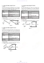
Page 71: ...is 1 00 Vp p 1 0 Vp p 0 04 0 02 Fig 7 2 1 0 Vp p 0 04 0 02 3 S Video Output S Y Level Check Purpose This check confirms that the video output level at the S video output connector is correct If this adjustment is made incorrectly picture will not be displayed correctly when the S video connector output signal is connected to TV using cable Mode Video level adjustment in test mode Signal Colour bar...

Page 72: ...Test point COMPONENT VIDEO OUT PB CB connector D1 D2 VIDEO OUT connector pin 3 terminated in 75Ω Instrument Oscilloscope Specification 700 50 mVp p Checking method 1 Insert the reference disk and play back the 100 colour bars 2 Confirm that the B Y level is 700 50 mVp p 1 0 0 05Vp p Fig 7 6 7 Component Video Output R Y Check Purpose This check confirms that the R Y signal of the component video ou...

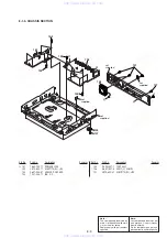
Page 73: ...1 EMBLEM NO 5 SONY 4 3 970 608 11 SUMITITE B3 BV 5 3 081 120 01 COVER FL 6 A 6061 470 A FL130 E COMPL 7 3 081 137 01 CURSOR 8 A 6071 047 A FR195 U COMPL 9 8 457 501 00 DRIVE DVD DW U11A 10 3 070 883 11 SCREW TAPPING 11 3 081 139 11 TOP CASE 12 3 632 494 01 RE USE CLAMP 13 A 6071 264 A RD045 U COMPL SVC 14 A 6061 471 A CN177 E COMPL 15 3 970 608 51 SUMITITE B3 BV Ref No Part No Description Remarks ...

Page 74: ...Y 64 3 081 130 01 SHAFT L 65 3 081 156 01 CUSHION DRIVE 66 3 080 678 11 PANEL BASE 67 3 081 119 02 SPRING GROUND 68 X 3953 197 1 BUTTON ASSY POWER 69 X 3953 196 1 BUTTON ASSY PLAY 70 3 081 428 01 CUSHION DOOR 71 3 083 631 11 DAMPER SOUND Ref No Part No Description Remarks Ref No Part No Description Remarks D D 51 52 54 55 54 61 57 53 68 67 54 71 65 69 63 66 58 70 56 70 60 54 62 59 64 www xiaoyu163...

Page 75: ...s composants identifiés par une marque 0 sont critiques pour la sécurité Ne les remplacer que par une pièce portant le numéro spécifié C C D D 107 107 102 102 107 106 105 103 104 103 101 1 not supplied not supplied not supplied not supplied 105 X 3953 201 1 FOOT ASSY 106 A 6071 051 A AV071 U COMPL 107 3 970 608 51 SUMITITE B3 BV www xiaoyu163 com QQ376315150 9 9 2 8 9 4 2 9 8 TEL 13942296513 9 9 2...

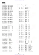
Page 76: ...162 970 11 CERAMIC CHIP 0 01uF 10 25V C314 1 127 715 91 CERAMIC CHIP 0 22uF 10 16V C315 1 126 947 11 ELECT 47uF 20 00 16V C323 1 107 737 11 MYLAR 560PF 5 00 50V C324 1 107 737 11 MYLAR 560PF 5 00 50V C326 1 162 923 11 CERAMIC CHIP 47PF 5 50V C329 1 130 472 00 MYLAR 0 0012uF 5 50V C330 1 130 472 00 MYLAR 0 0012uF 5 50V C331 1 126 960 11 ELECT 1uF 20 00 50V C338 1 126 947 11 ELECT 47uF 20 00 16V C34...

Page 77: ...38 1 107 826 11 CERAMIC CHIP 0 1uF 10 00 16V C739 1 125 838 11 CERAMIC CHIP 2 2uF 10 6 3V C740 1 164 227 11 CERAMIC CHIP 0 022uF 10 25V C741 1 162 964 11 CERAMIC CHIP 0 001uF 10 50V C743 1 162 968 11 CERAMIC CHIP 0 0047uF 10 50V C745 1 107 826 11 CERAMIC CHIP 0 1uF 10 00 16V C746 1 126 947 11 ELECT 47uF 20 00 16V C748 1 162 966 11 CERAMIC CHIP 0 0022uF 10 50V C753 1 126 947 11 ELECT 47uF 20 00 16V...

Page 78: ... TL IC802 6 701 820 01 IC LA73053 TLM E IC1101 8 759 349 01 IC MC68HC68VBIFB JACK J601 1 764 188 21 JACK SMALL TYPE DIA 3 5 J801 1 785 535 11 JACK BLOCK PIN J802 1 785 535 11 JACK BLOCK PIN J805 1 815 360 11 JACK PIN 3P COMPONENT OUT JUMPER RESISTOR JR001 1 216 295 91 SHORT CHIP 0 JR002 1 216 296 11 SHORT CHIP 0 JR003 1 216 296 11 SHORT CHIP 0 JR004 1 216 296 11 SHORT CHIP 0 JR005 1 216 295 91 SHO...

Page 79: ... 11 METAL CHIP 0 5 1 16W R112 1 216 210 00 RES CHIP 3 3K 5 1 8W R113 1 216 833 11 METAL CHIP 10K 5 1 16W R114 1 216 296 11 SHORT CHIP 0 R115 1 216 296 11 SHORT CHIP 0 R116 1 216 295 91 SHORT CHIP 0 R117 1 216 295 91 SHORT CHIP 0 R118 1 216 295 91 SHORT CHIP 0 R120 1 216 296 11 SHORT CHIP 0 R121 1 216 295 91 SHORT CHIP 0 R123 1 208 818 11 METAL CHIP 33K 0 5 1 10W R124 1 208 808 11 METAL CHIP 12K 0 ...

Page 80: ...P 1K 5 1 16W R431 1 216 821 11 METAL CHIP 1K 5 1 16W R432 1 216 809 11 METAL CHIP 100 5 1 16W R437 1 216 864 11 METAL CHIP 0 5 1 16W R438 1 216 833 11 METAL CHIP 10K 5 1 16W R439 1 216 821 11 METAL CHIP 1K 5 1 16W R440 1 218 446 11 METAL CHIP 1 5 1 10W R441 1 216 857 11 METAL CHIP 1M 5 1 16W R450 1 216 817 11 METAL CHIP 470 5 1 16W R451 1 216 817 11 METAL CHIP 470 5 1 16W R454 1 216 295 91 SHORT C...

Page 81: ...CHIP 3 9K 5 1 16W R728 1 216 829 11 METAL CHIP 4 7K 5 1 16W R729 1 216 822 11 METAL CHIP 1 2K 5 1 16W R730 1 216 826 11 METAL CHIP 2 7K 5 1 16W R731 1 216 817 11 METAL CHIP 470 5 1 16W R732 1 216 828 11 METAL CHIP 3 9K 5 1 16W R733 1 216 857 11 METAL CHIP 1M 5 1 16W R734 1 216 829 11 METAL CHIP 4 7K 5 1 16W R735 1 216 823 11 METAL CHIP 1 5K 5 1 16W R742 1 216 821 11 METAL CHIP 1K 5 1 16W R743 1 21...

Page 82: ...1 METAL CHIP 100 5 1 16W R1213 1 216 809 11 METAL CHIP 100 5 1 16W R1217 1 216 833 11 METAL CHIP 10K 5 1 16W R2601 1 216 833 11 METAL CHIP 10K 5 1 16W R2602 1 216 853 11 METAL CHIP 470K 5 1 16W R2603 1 216 833 11 METAL CHIP 10K 5 1 16W R2604 1 216 833 11 METAL CHIP 10K 5 1 16W TRANSFORMER T601 1 439 651 11 TRANSFORMER DC DC CONVERTER TUNER TU401 8 598 612 00 TUNER FSS BTF DA401 VIBRATOR X601 1 781...

Page 83: ...2 8 729 421 22 TRANSISTOR UN2211 TX RESISTOR R101 1 216 819 11 METAL CHIP 680 5 1 16W R102 1 216 864 11 METAL CHIP 0 5 1 16W R106 1 216 825 11 METAL CHIP 2 2K 5 1 16W R107 1 216 821 11 METAL CHIP 1K 5 1 16W R108 1 216 821 11 METAL CHIP 1K 5 1 16W R109 1 216 821 11 METAL CHIP 1K 5 1 16W R110 1 216 821 11 METAL CHIP 1K 5 1 16W R112 1 216 825 11 METAL CHIP 2 2K 5 1 16W R113 1 216 825 11 METAL CHIP 2 ...

Page 84: ...C415 1 107 826 11 CERAMIC CHIP 0 1uF 10 00 16V C416 1 107 826 11 CERAMIC CHIP 0 1uF 10 00 16V C419 1 107 826 11 CERAMIC CHIP 0 1uF 10 00 16V C420 1 107 826 11 CERAMIC CHIP 0 1uF 10 00 16V C421 1 107 826 11 CERAMIC CHIP 0 1uF 10 00 16V C422 1 107 826 11 CERAMIC CHIP 0 1uF 10 00 16V C423 1 124 779 00 ELECT CHIP 10uF 20 16V C424 1 107 826 11 CERAMIC CHIP 0 1uF 10 00 16V C425 1 107 826 11 CERAMIC CHIP...

Page 85: ...109 1 127 715 91 CERAMIC CHIP 0 22uF 10 16V C1110 1 127 715 91 CERAMIC CHIP 0 22uF 10 16V C1111 1 127 715 91 CERAMIC CHIP 0 22uF 10 16V C1112 1 127 715 91 CERAMIC CHIP 0 22uF 10 16V C1113 1 127 715 91 CERAMIC CHIP 0 22uF 10 16V C1114 1 127 715 91 CERAMIC CHIP 0 22uF 10 16V C1115 1 127 715 91 CERAMIC CHIP 0 22uF 10 16V C1116 1 127 715 91 CERAMIC CHIP 0 22uF 10 16V C1117 1 127 715 91 CERAMIC CHIP 0 ...

Page 86: ...61 21 ELECT CHIP 100uF 20 10V C2002 1 107 826 11 CERAMIC CHIP 0 1uF 10 00 16V C2003 1 107 826 11 CERAMIC CHIP 0 1uF 10 00 16V C2005 1 126 607 11 ELECT CHIP 47uF 20 4V C2006 1 107 826 11 CERAMIC CHIP 0 1uF 10 00 16V C2007 1 107 826 11 CERAMIC CHIP 0 1uF 10 00 16V C2008 1 107 826 11 CERAMIC CHIP 0 1uF 10 00 16V C2009 1 107 826 11 CERAMIC CHIP 0 1uF 10 00 16V C2010 1 162 913 11 CERAMIC CHIP 8PF 0 50P...

Page 87: ... CHIP 0 1uF 10 00 16V C2322 1 127 715 91 CERAMIC CHIP 0 22uF 10 16V C2323 1 127 715 91 CERAMIC CHIP 0 22uF 10 16V C2324 1 126 209 11 ELECT CHIP 100uF 20 00 4V C2325 1 127 715 91 CERAMIC CHIP 0 22uF 10 16V C2328 1 164 173 11 CERAMIC CHIP 0 0039uF 10 50V C2329 1 107 826 11 CERAMIC CHIP 0 1uF 10 00 16V C2330 1 107 826 11 CERAMIC CHIP 0 1uF 10 00 16V C2331 1 115 414 11 CERAMIC CHIP 820PF 5 00 25V C233...

Page 88: ...ZC 1HT IC708 8 759 679 55 IC SN74LVC08APWR IC903 6 703 412 01 IC uPD61052GD LML IC906 8 759 589 36 IC MT48LC4M16A2TG 75 IC907 8 759 589 36 IC MT48LC4M16A2TG 75 IC1001 6 703 504 01 IC CXD9754R IC1002 6 703 434 01 IC CV VCP102 IC1101 6 703 719 01 IC CXD9736GG IC1202 6 702 300 01 IC TK11118CSCL G IC1203 8 752 416 45 IC XD1935Q IC1204 6 700 098 01 IC HY57V641620HGT P TR V IC1205 6 703 461 11 IC CY2309...

Page 89: ...1 RES CHIP 47 5 1 16W R190 1 218 937 11 RES CHIP 47 5 1 16W R191 1 218 937 11 RES CHIP 47 5 1 16W R192 1 218 937 11 RES CHIP 47 5 1 16W R193 1 218 937 11 RES CHIP 47 5 1 16W R194 1 218 937 11 RES CHIP 47 5 1 16W R195 1 218 937 11 RES CHIP 47 5 1 16W R196 1 218 937 11 RES CHIP 47 5 1 16W R197 1 218 933 11 RES CHIP 22 5 1 16W R198 1 218 935 11 RES CHIP 33 5 1 16W R199 1 218 937 11 RES CHIP 47 5 1 16...

Page 90: ...0 1 218 990 11 SHORT CHIP 0 R731 1 218 965 11 RES CHIP 10K 5 1 16W R732 1 218 965 11 RES CHIP 10K 5 1 16W R735 1 218 935 11 RES CHIP 33 5 1 16W R737 1 218 935 11 RES CHIP 33 5 1 16W R738 1 218 935 11 RES CHIP 33 5 1 16W R740 1 218 935 11 RES CHIP 33 5 1 16W R742 1 218 935 11 RES CHIP 33 5 1 16W R744 1 218 935 11 RES CHIP 33 5 1 16W R745 1 218 935 11 RES CHIP 33 5 1 16W R746 1 218 935 11 RES CHIP 3...

Page 91: ...33 11 RES CHIP 22 5 1 16W R1129 1 218 990 11 SHORT CHIP 0 R1130 1 218 933 11 RES CHIP 22 5 1 16W R1131 1 218 990 11 SHORT CHIP 0 R1144 1 218 990 11 SHORT CHIP 0 R1150 1 218 990 11 SHORT CHIP 0 R1151 1 218 990 11 SHORT CHIP 0 R1153 1 218 990 11 SHORT CHIP 0 R1154 1 218 990 11 SHORT CHIP 0 R1155 1 218 990 11 SHORT CHIP 0 R1156 1 218 990 11 SHORT CHIP 0 R1157 1 218 990 11 SHORT CHIP 0 R1158 1 218 990...

Page 92: ... 1 16W R1646 1 208 635 11 RES CHIP 10 5 1 16W R1651 1 218 941 81 RES CHIP 100 5 1 16W R1655 1 218 938 11 RES CHIP 56 5 1 16W R1660 1 218 938 11 RES CHIP 56 5 1 16W R1675 1 218 990 11 SHORT CHIP 0 R1685 1 218 937 11 RES CHIP 47 5 1 16W R1688 1 218 938 11 RES CHIP 56 5 1 16W R1701 1 216 295 91 SHORT CHIP 0 R1702 1 216 295 91 SHORT CHIP 0 R1703 1 216 295 91 SHORT CHIP 0 R1704 1 216 295 91 SHORT CHIP ...

Page 93: ...ES CHIP 33 5 1 16W R2196 1 218 957 11 RES CHIP 2 2K 5 1 16W R2201 1 218 953 11 RES CHIP 1K 5 1 16W R2202 1 216 296 11 SHORT CHIP 0 R2205 1 216 296 11 SHORT CHIP 0 R2206 1 216 296 11 SHORT CHIP 0 R2208 1 218 965 11 RES CHIP 10K 5 1 16W R2209 1 218 941 81 RES CHIP 100 5 1 16W R2211 1 218 941 81 RES CHIP 100 5 1 16W R2214 1 218 965 11 RES CHIP 10K 5 1 16W R2219 1 218 932 11 RES CHIP 18 5 1 16W R2220 ...

Page 94: ...1 16W R3101 1 218 935 11 RES CHIP 33 5 1 16W R3102 1 218 961 11 RES CHIP 4 7K 5 1 16W R3103 1 218 961 11 RES CHIP 4 7K 5 1 16W R3106 1 218 990 11 SHORT CHIP 0 R3107 1 218 990 11 SHORT CHIP 0 R3112 1 218 965 11 RES CHIP 10K 5 1 16W R3113 1 218 965 11 RES CHIP 10K 5 1 16W R3114 1 218 965 11 RES CHIP 10K 5 1 16W R3120 1 218 990 11 SHORT CHIP 0 R3121 1 218 990 11 SHORT CHIP 0 R3124 1 218 990 11 SHORT ...

Page 95: ...TWORK 33X4 1005 RB421 1 242 963 21 RES NETWORK 33X4 1005 RB422 1 242 963 21 RES NETWORK 33X4 1005 RB423 1 242 963 21 RES NETWORK 33X4 1005 RB424 1 242 963 21 RES NETWORK 33X4 1005 RB425 1 242 963 21 RES NETWORK 33X4 1005 RB426 1 242 963 21 RES NETWORK 33X4 1005 RB427 1 233 270 11 NETWORK RES 8 GANG 10K RB428 1 242 963 21 RES NETWORK 33X4 1005 RB429 1 242 963 21 RES NETWORK 33X4 1005 RB430 1 242 96...

Page 96: ...fety Replace only with part number specified Note Les composants identifiés par une marque 0 sont critiques pour la sécurité Ne les remplacer que par une pièce portant le numéro spécifié RD 045 ACCESSORIES PACKING MATERIALS 1 477 804 31 REMOTE COMMANDER RMT D203A 1 751 271 11 CORD CONNECTION AV CABLE 1 765 635 71 CORD CONNECTION NTSC 0 1 823 701 11 CORD POWER 3 071 119 81 LID CASE BATTERY FOR RMT ...

Page 97: ... 1 2003 6 Published by Customer Support Center www xiaoyu163 com QQ376315150 9 9 2 8 9 4 2 9 8 TEL 13942296513 9 9 2 8 9 4 2 9 8 0 5 1 5 1 3 6 7 3 Q Q TEL 13942296513 QQ 376315150 892498299 TEL 13942296513 QQ 376315150 892498299 http www xiaoyu163 com http www xiaoyu163 com ...

Reviews: