1-27
108
For details on how to dub when this recorder
is connected to other video equipment having
DV jacks, see page 77.
The DV jack on this recorder can only input
DVC-SD signals. It cannot output signals.
The DV jack will not accept MICRO MV
signals from equipment such as a MICRO
MV digital video camera with an i.LINK
jack.
For further precautions, see the notes on
page 77.
For details on precautions when connecting
this recorder, also see the instruction manuals
for the equipment to be connected.
Use the Sony i.LINK 4-pin-to-4-pin cable
(during DV dubbing).
i.LINK and are trademarks.
i.LINK functions on this
recorder
Required i.LINK cable
109
Addi
tion
al
Inf
o
rm
a
tion
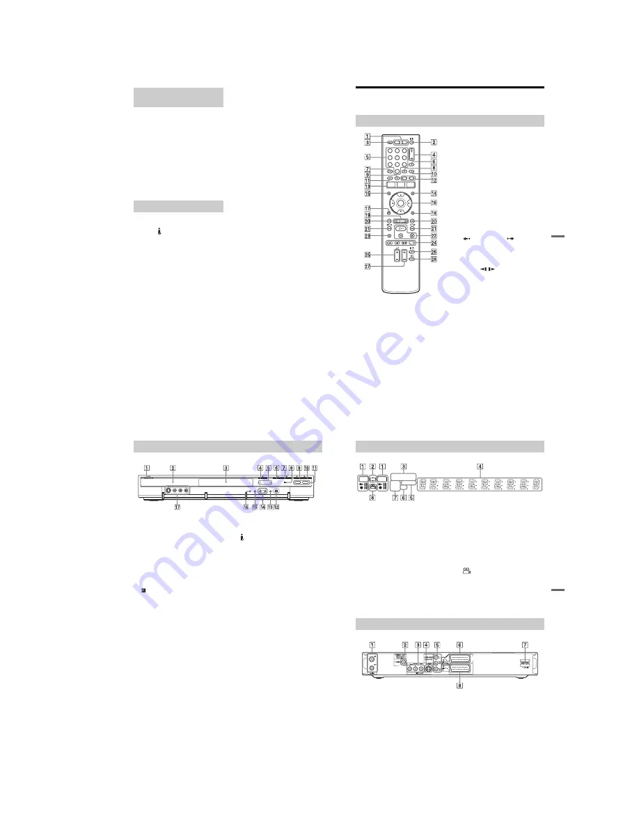
Guide to Parts and Controls
For more information, see the pages in parentheses.
A
HDD button (27)
DVD button (27)
B
[
/
1
(on/standby) button (20)
C
Z
(open/close) button (27)
D
PROG (programme) +/– buttons (27)
The + button has a tactile dot
*.
E
Number buttons (44, 58)
The number 5 button has a tactile dot
*.
F
INPUT SELECT button (51, 77)
G
AUDIO button (54)
The AUDIO button has a tactile dot
*.
H
SUBTITLE button (54)
I
MENU button (52)
J
TV/DVD button (17)
K
TOP MENU button (52)
L
CHAPTER MARK button (67)
CHAPTER MARK ERASE button
(67)
M
SYSTEM MENU button (80, 83)
TITLE LIST button (29, 52, 64)
TIMER button (42, 44)
N
TIMER LIST button (47)
O
DISPLAY button (31)
P
<
/
M
/
m
/
,
/ENTER button (20)
Q
O
RETURN button (47)
R
OPTIONS button (38)
S
(instant replay)/
(instant
advance) buttons (29, 59)
T
.
/
>
(previous/next) buttons
(54)
U
mc
/
CM
(search/slow/
freeze frame) buttons (54)
V
H
(play) button (52)
X
(pause) button (54)
x
(stop) button (52)
The
H
button has a tactile dot*.
W
TIME/TEXT button (31)
X
z
REC button (27)
x
REC STOP button (27)
c
z
SYNCHRO REC button (49)
REC MODE button (27)
Y
TV
2
(volume) +/– buttons (17)
Z
TV
[
/
1
(on/standby) button (17)
wj
TV PROG (programme) +/– buttons
(17)
The + button has a tactile dot
*.
wk
TV
t
button (17)
* Use the tactile dot as a reference when operating
the recorder.
Remote
1
2
3
4
5
6
7
8
9
0
,
continued
110
A
[
/
1
(on/standby) button (20)
B
Front panel display (111)
C
Disc tray (27)
D
A
(open/close) button (27)
E
TIMER REC indicator (42)
SYNCHRO REC indicator (49)
F
H
(play) button (52)
G
x
(stop) button (52)
H
(remote sensor) (17)
I
z
REC button (27)
J
x
REC STOP button (27)
K
HDD button/indicator (27)
DVD button/indicator (27)
L
DV IN jack (77)
M
ONE-TOUCH DUB button (79)
N
P/– buttons (27)
The + button has a tactile dot
*.
O
INPUT SELECT button (49, 77)
P
REC MODE button (27)
Q
LINE 2 IN (S VIDEO/VIDEO/
L(MONO) AUDIO R) jacks (22)
* Use the tactile dot as a reference when operating
the recorder.
Front panel
111
Addi
tion
al
Inf
o
rm
a
tion
A
HDD/DVD indicators
Displays the selected media and the
playing/recording status.
B
Dubbing direction indicator
C
SMARTLINK indicator (14)
D
Displays the following:
• Playing time/remaining time
• Current title/chapter/track/index
number
• Recording time/recording mode
• Clock
• Programme position
• TV Direct Rec indication
(27):
“TV” appears in the right most two
digits.
E
NICAM indicator (41)
F
TV indicator (27)
G
Disc type*
H
(angle) indicator (52)
* Displays DATA CDs as “CD.”
z
Hint
You can turn off the front panel display when the recorder is turned off by setting “Dimmer” to “Save
Power” in the “Others” setup (page 96).
A
AERIAL IN/OUT jacks (12)
B
DIGITAL OUT (COAXIAL) jack (15)
C
LINE 2 OUT (R-AUDIO-L/VIDEO)
jacks (13, 15)
D
LINE 2 OUT (S VIDEO) jack (13)
E
COMPONENT VIDEO OUT (Y, P
B
/
C
B
, P
R
/C
R
) jacks (13)
F
LINE 3/DECODER jack (13)
G
AC IN terminal (16)
H
LINE 1 – TV jack (13)
Front panel display
HDD
SMARTLINK
DVD
VCD
NICAM
TV
DVD
Rear panel
Summary of Contents for RDR-HX520
Page 6: ...MEMO 6 ...


