1-7
28
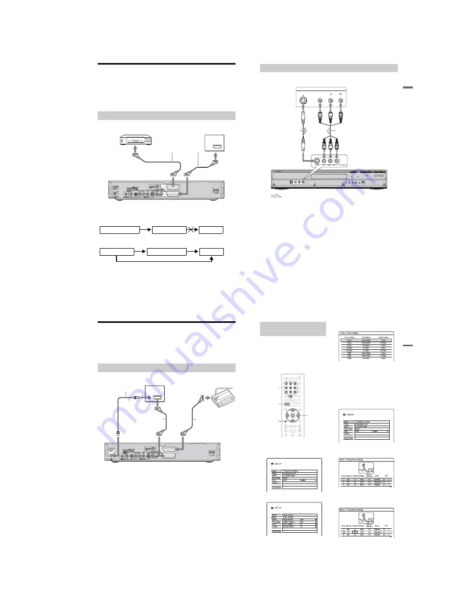
Connecting a VCR or Similar Device
After disconnecting the recorder’s mains lead from the mains, connect a VCR or similar
recording device to the LINE IN jacks of this recorder.
Use the DV IN jack on the front panel if the equipment has a DV output jack (i.LINK jack)
(page 91).
For details, refer to the instruction manual supplied with the connected equipment.
To record on this recorder, see “Recording from connected equipment without a timer” on
page 65.
Connect a VCR or similar recording device to the LINE 3/DECODER jack of this recorder.
b
Notes
• Pictures containing copy protection signals that prohibit any copying cannot be recorded.
• If you pass the recorder signals through a VCR, you may not receive a clear image on your TV screen.
Be sure to connect your VCR to the DVD recorder and to your TV in the order shown below. To watch
video tapes, watch the tapes through a second line input on your TV.
• The SMARTLINK features are not available for devices connected via the DVD recorder’s LINE 3/
DECODER jack.
• When you record to a VCR from this DVD recorder, do not switch the input source to TV by pressing the
TV/DVD button on the remote.
• If you disconnect the recorder’s mains lead, you will not be able to view the signals from the connected
VCR.
Connecting to the LINE 3/DECODER jack
TV
DVD recorder
to
i
LINE 1 – TV
VCR
to
i
LINE 3/DECODER
SCART cord (not supplied)
to SCART input
VCR
DVD recorder
TV
Line input 1
Line input 2
DVD recorder
VCR
TV
29
H
ook
up
s
and
Se
tti
n
gs
Connect a VCR or similar recording device to the LINE 2 IN jacks of this recorder. If the
equipment has an S-video jack, you can use an S-video cord instead of an audio/video cord.
z
Hint
When the connected equipment outputs only monaural sound, connect to just the L(MONO) and VIDEO
input jacks on the front of the recorder. Do not connect the R input jack.
b
Notes
• Do not connect the yellow LINE IN (VIDEO) jack when using an S-video cord.
• Do not connect the output jack of this recorder to another equipment’s input jack with the other
equipment’s output jack connected to the input jack of this recorder. This may cause noise (feedback).
• Do not connect more than one type of video cord between the recorder and your TV at the same time.
Connecting to the LINE 2 IN jacks on the front panel
OUTPUT
S VIDEO
AUDIO
L
R
VIDEO
VCR, etc.
Audio/video cord
(not supplied)
S-video cord
(not supplied)
DVD recorder
: Signal flow
to LINE 2 IN
30
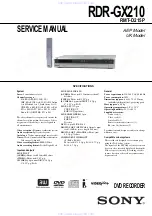
Connecting a PAY-TV/Canal Plus Analogue Decoder
You can watch or record PAY-TV/Canal Plus analogue decoder programmes if you connect a
decoder (not supplied) to the recorder. Disconnect the recorder’s mains lead from the mains
when connecting the decoder. Note that when you set “Line3 Input” to “Decoder” in step 5 of
“Setting PAY-TV/Canal Plus analogue programme positions” (page 31), you will not be able
to select “L3” because Line 3 will become a dedicated line for the decoder.
Connecting a decoder
TV
Aerial cable
(supplied)
SCART cord
(not supplied)
PAY-TV/Canal Plus
analogue decoder
to AERIAL OUT
to
i
LINE 3/DECODER
DVD recorder
to AERIAL IN
to SCART input
SCART cord
(not supplied)
to
i
LINE 1 – TV
31
H
ook
up
s
and
Se
tti
n
gs
To watch or record PAY-TV/Canal Plus
analogue programmes, set your recorder to
receive the programme positions using the
on-screen display.
In order to set the programme positions
correctly, be sure to follow all of the steps
below.
1
Press SYSTEM MENU.
The System Menu appears.
2
Select “SETUP,” and press ENTER.
3
Select “Video,” and press ENTER.
4
Select “Scart Setting,” and press
ENTER.
5
Press
M
/
m
to select “Video” or “RGB”
for “Line1 Output,” “Decoder” for
“Line3 Input,” and “Video” for “Line3
Output,” and press ENTER.
The “Video” setup display appears again.
6
Press
O
RETURN to return the cursor
to the left column.
7
Select “Basic,” and press ENTER.
8
Select “Programme Setting,” and
press ENTER.
9
Press
M
/
m
to select the desired
programme position, and press
ENTER.
Setting PAY-TV/Canal Plus
analogue programme positions
SYSTEM
MENU
O
RETURN
<
/
M
/
m
/
,
,
ENTER
Number
buttons
,
continued
Summary of Contents for RDR-HX820
Page 38: ...1 32E MEMO ...
Page 52: ...RDR HX820 HX825 MEMO 3 11 3 12E ...
Page 91: ...5 12E Pin No Pin Name I O Function Y25 VSS Digital GND ...


