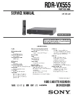
background image

SERVICE MANUAL

VIDEO CASSETTE RECORDER/

DVD RECORDER

SPECIFICATIONS

RMT-D240A

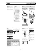
Refer to the SERVICE MANUAL of VHS MECHANI-

CAL ADJUSTMENT MANUAL VII for MECHANICAL

ADJUSTMENTS. (9-921-790-11)

— Continued on next page —

RDR-VX555

US Model

DX-13A MECHANISM

System

[DVD recorder section]

Laser

Semiconductor laser

Audio recording format

Dolby Digital

Video recording format

MPEG Video

[VCR section]

Format

VHS NTSC standard

Video recording system

Rotary head helical scanning FM system

Video heads

Double azimuth four heads

Video signal

NTSC color, EIA standards

Tape speed

SP: 33.35 mm/s (1 /

inches/s)

3

EP: 11.12 mm/s ( /

16 

inches/s)

7

LP: 16.67 mm/s (   /

16 

inches/s), 

11

playback only

Maximum recording/playback time

8 hrs. in EP mode (with T-160 tape)

Rewind time

Approx. 2 min (with T-120 tape)

[Timer section]

Clock

Quartz locked

Timer indication

12-hour cycle

Timer setting

12 programs in total (max.)

Inputs and outputs

LINE 1 IN and LINE 2 IN

VIDEO IN, phono jack (1 each)
Input signal: 1 Vp-p, 75 ohms, unbalanced, 
sync negative
AUDIO IN, phono jacks (2 each)
Input level: 327 mVrms
Input impedance: more than 47 kilohms

LINE 2 IN

S VIDEO, 4-pin, mini-DIN jack
Y: 1.0 Vp-p, unbalanced, sync negative
C: 0.286 Vp-p, load impedance 75 ohms
DV IN, 4-pin jack, i.LINK S100

LINE OUT

VIDEO OUT, phono jack (1)
Output signal: 1 Vp-p, 75 ohms, 
unbalanced, sync negative
AUDIO OUT, phono jacks (2)
Standard output: 327 mVrms
Load impedance: 47 kilohms
Output impedance: less than 10 kilohms

DIGITAL AUDIO OUT

OPTICAL, Optical output jack
–18 dBm (wave length: 660 nm)
COAXIAL, phono jack
Output signal: 0.5 Vp-p, 75 ohms

Summary of Contents for RDR VX555 - DVDr/ VCR Combo

Page 1: ...ording playback time 8 hrs in EP mode with T 160 tape Rewind time Approx 2 min with T 120 tape Timer section Clock Quartz locked Timer indication 12 hour cycle Timer setting 12 programs in total max Inputs and outputs LINE 1 IN and LINE 2 IN VIDEO IN phono jack 1 each Input signal 1 Vp p 75 ohms unbalanced sync negative AUDIO IN phono jacks 2 each Input level 327 mVrms Input impedance more than 47...

Page 2: ...consumption 31 W Power back up Back up duration 30 min Operating temperature 5 C to 35 C 41 F to 95 F Storage temperature 20 C to 60 C 4 F to 140 F Operating humidity 25 to 80 Dimensions including projecting parts and controls w h d Approx 430 82 332 mm Approx 17 3 1 4 13 1 8 inches Mass Approx 4 7 kg Approx 10 4 lbs Supplied accessories Remote commander remote 1 Size AA R6 batteries 2 Audio video...

Page 3: ...ea of your repair for unsoldered or poorly soldered connections Check the entire board surface for solder splashes and bridges 2 Check the interboard wiring to ensure that no wires are pinched or contact high wattage resistors 3 Look for unauthorized replacement parts particularly transistors that were installed during a previous repair Point them out to the customer and recommend their replacemen...

Page 4: ...l 2 14 2 4 16 Ass y Holder Clutch Removal 2 14 2 4 17 Ass y Lever Up Down Ass y Gear Center Removal 2 15 2 4 18 Guide Cassette Door Removal 2 15 2 4 19 Ass y Lever Unit Pinch Plate Joint Spring Pinch Drive Removal 2 16 2 4 20 Ass y Lever 9 Guide Removal 2 16 2 4 21 FE Head Removal 2 17 2 4 22 Ass y ACE Head Removal 2 17 2 4 23 Ass y Slider S T Removal 2 18 2 4 24 Plate Ground Deck Ass y Cylinder R...

Page 5: ...e customer 4 Insulation Resistance Test Cold Check 1 Unplug the power supply cord and connect a jumper wire between the two prongs of the plug 2 Turn on the power switch of the instrument 3 Measure the resistance with an ohmmeter between the jumpered AC plug and all exposed metallic cabinet parts on the instrument such as screwheads antenna control shafts handle brackets etc When an exposed metall...

Page 6: ... them with components rated for higher voltage wattage etc Parts that have special safety characteristics are identified by shading an or a on schematics and parts lists Use of a substitute replacement that does not have the same safety characteristics as the recommended replacement part might create shock fire and or other hazards Product safety is under review continuously and new instructions a...

Page 7: ...he service precautions are indicated or printed on the cabinet chassis or components When servicing follow the printed or indicated service precautions and service materials 3 The components used in the unit have a specified flame resistance and dielectric strength When replacing components use components which have the same ratings Components identified by shading by or by in the circuit diagram ...

Page 8: ...sembly 3 Use only a grounded tip soldering iron to solder or unsolder ESD devices 4 Use only an anti static solder removal devices Some solder removal devices not classified as anti static can generate electrical charges sufficient to damage ESD devices 5 Do not use freon propelled chemicals These can generate electrical charges sufficient to damage ESD devices 6 Do not remove a replacement ESD de...

Page 9: ...s them the same ground as the sheet 4 Remove the optical pick up block 5 Perform work on top of the conductive sheet Be careful not to let your clothes or any other static sources to touch the unit Be sure to put on a wrist strap grounded to the sheet Be sure to lay a conductive sheet made of copper etc Which is grounded to the table Fig 3 6 Short the short terminal on the PCB which is inside the ...

Page 10: ...MORY used on the DVD Main board was replaced Resetting method 1 Enter the Adjustment mode and press two times the 1 button on the remote commander For an entering method of Adjustment mode see 6 1 VCR Adjustment The tray will automatically open and the version information will be displayed on the TV screen 2 Turn the power off ...

Page 11: ...e Simultaneous Operations VCR Playback VCR Recording DVD Playback DVD Recording Playing a VHS tape 1 No No Yes Recording on a VHS tape No Yes Yes 3 Playing a DVD 2 No Yes No Recording on a DVD Yes Yes 3 No 10 How to Use the On Screen Menus The following three displays are mainly used to operate this recorder Once you become familiar with the basic operations you will find the recorder easy to use ...

Page 12: ...cord TV programs You cannot record on this recorder if you have a cable box or satellite receiver without audio video outputs cable with no cable box antenna only no cable TV In the cases above contact your cable service or satellite service company to see if they can provide you with a compatible cable box or satellite receiver Using the cable box satellite receiver control function This function...

Page 13: ...E OUT VIDEO Y L PB R PR AUDIO LINE 1 IN AUDIO OUT SVIDEO OUT COMPONENT VIDEO OUT DIGITAL AUDIO OUT OPTICAL COAXIAL HDMI OUT SETTOP BOX CONTROL HDMI IN HDMI OUT TV or projector HDMI cord not supplied to HDMI OUT Signal flow VCR DVD recorder to HDMI input 17 Hookups and Settings If your TV has component video input jacks Connect the COMPONENT VIDEO OUT jacks using a component video cord not supplied...

Page 14: ...t new batteries Do not expose the remote sensor marked on the front panel to strong light such as direct sunlight or lighting apparatus The recorder may not respond to the remote With normal use the batteries should last about three to six months Do not leave the remote in an extremely hot or humid place Do not drop any foreign object into the remote casing particularly when replacing the batterie...

Page 15: ...tup No Disc OK Cancel Enter the brand code of your set top box Select the input line that you connected the set top box to Line1 Line2 Easy Setup No Disc Hour Min AM PM Month Set the time and date manually Day Year 00 AM 12 01 01 2007 Mon No Disc Easy Setup 12 00 AM 01 25 Hookups and Settings 11Select the setting that matches your TV type 16 9 For wide screen TVs or standard TVs with a wide screen...

Page 16: ...o not connect the output jack of this recorder to another equipment s input jack with the other equipment s output jack connected to the input jack of this recorder Noise feedback may result If you pass the recorder signals via the VCR you may not receive a clear image on your TV screen Be sure to connect your VCR to the VCR DVD recorder and your TV in the order shown below To watch video tapes wa...

Page 17: ...ATA CD DATA DVD continued 34 Note on playback operations of DVD VIDEOs VIDEO CDs Some playback operations of DVD VIDEOs VIDEO CDs may be intentionally set by software producers Since this recorder plays DVD VIDEOs VIDEO CDs according to the disc contents the software producers designed some playback features may not be available Also see the instructions supplied with the DVD VIDEOs VIDEO CDs Note...

Page 18: ...of the recorder Notes on playing DVDs with a DTS soundtrack DTS audio signals are output only through the DIGITAL AUDIO OUT COAXIAL or OPTICAL HDMI OUT jack When you play a DVD with DTS soundtracks set Digital Out DTS to On of Audio in the Setup display page 98 If you connect the recorder to audio equipment without a DTS decoder do not set DTS to On in Audio setup A loud noise or no sound may come...

Page 19: ...n play MP3 audio tracks on DATA CDs or DATA DVDs 1 Press DVD to operate the DVD recorder 2 Place a DATA CD DATA DVD on the disc tray When you insert a DATA CD DATA DVD containing MP3 audio tracks and JPEG image files the display for selecting a media type appears When you select Mix you can enjoy a slide show with sound page 43 If you insert a DATA CD DATA DVD containing only MP3 audio tracks the ...

Page 20: ...on Technology Industries Association Displaying the Playing Time and Play Information You can check disc information such as playing time recording mode and remaining disc space Press DISPLAY The information display appears Each time you press the button the display changes as follows Disc and tape information date and time m Disc information only m No display DVD A Playing status B Playing time C...

Page 21: ...panel display The recorder returns to normal recording mode To stop recording Press x STOP twice Note that it may take a few seconds for the recorder to stop recording HQ SP HSP LSP SLP LP EP ESP 0 30 1 00 7 30 8 00 Normal recording 49 DVD Recording Checking the disc status while recording You can check the recording information such as recording time or disc type Press DISPLAY during recording Th...

Page 22: ... the program that starts later will be cut Notes The recorder starts recording only after detecting the video signal from the connected equipment The beginning of the program may not be recorded regardless of whether or not the recorder s power is on or off To use the connected equipment during Synchro Rec standby cancel the standby mode by pressing SYNCHRO REC To return to standby mode again be s...

Page 23: ...dit functions available for Playlist titles are Renaming a title page 60 Erasing a title page 57 Erasing a chapter page 58 Erasing a section of a title A B Erase page 58 Editing a Playlist scene page 63 Dividing a title page 59 Combining titles page 64 z Hint You can switch the Title List to show original or Playlist While the Title List menu is turned on press ORIGINAL PLAYLIST repeatedly Notes Y...

Page 24: ...ry 3 Select a title and press ENTER The sub menu appears 4 Select Title Name and press ENTER The Title Name display appears 10 10 AM Title No 01 T 00 00 10 Divide Title Original Title No 01 End 00 00 10 Start 00 00 00 Point Divide May 02 2007 08 00 PM R RWVR RWVideo RW RVR RVideo 1 1 2 2 3 3 4 4 5 5 6 6 7 7 8 8 0 0 9 9 M m ENTER O RETURN TITLE LIST DVD ORIGINAL PLAYLIST Title Name K _ A B C D E F ...

Page 25: ...f the selected scene RWVR RVR Playlist 10 10 AM LINE 1 03 25 PM May 02 2007 T No Title Length Edit 01 LINE 1 00 05 04 02 LINE 1 00 00 51 03 LINE 1 01 59 00 04 LINE 1 00 58 56 1 4 Playlist 10 10 AM 11 30 PM May 15 2007 T No Title Length Edit 01 LINE 1 00 05 04 02 LINE 1 00 00 51 03 LINE 1 01 59 00 04 LINE 1 00 58 56 3 4 LINE 1 RWVR RVR RWVR RVR 65 DVD Editing 1 Follow steps 1 to 7 of Editing a Play...

Page 26: ...sc after you first record on it You cannot mix VR mode and Video mode on the same DVD RW or DVD R You cannot change the recording format on used DVD Rs The recorder records on new DVD Rs in Video mode unless you first format the discs in VR mode page 47 69 VCR Playback VCR Playback Playing a VHS Tape 1 Press VIDEO to operate the VCR 2 Insert a tape Playback starts automatically if you insert a tap...

Page 27: ...gnize the end of a blank space depending on its length No index signal is marked if you pause a recording and then keep recording the same program To mark an index press x STOP or change the input source once during recording pause 1 1 2 2 3 3 4 4 5 5 6 6 7 7 8 8 0 0 9 9 M m ENTER H PLAY VIDEO OPTIONS CLEAR ENTER Enter Go To Zero End Search Forward Intro Scan Reverse Intro Scan Move 0 00 00 Go to ...

Page 28: ...CR 2 Press z REC repeatedly to set the duration Each press increases the time by 30 minutes up to six hours 1 1 2 2 3 3 4 4 5 5 6 6 7 7 8 8 0 0 9 9 REC MODE H PLAY X PAUSE x STOP z REC VIDEO CH DVD INPUT DISPLAY 0 30 1 00 5 30 6 00 Normal recording 77 VCR Recording c and OTR light up and the remaining recording time appears in the front panel display When the time counter reaches 0 00 the recorder...

Page 29: ...ording stops and the recorder turns off To stop recording Press x STOP twice To cancel Synchro Rec function Press SYNCHRO REC before recording starts The SYNCHRO REC indicator on the recorder turns off If you press SYNCHRO REC during Synchro Rec the recording stops the SYNCHRO REC indicator turns off and the recorder turns off If the timer settings of a Synchro Recording and another timer recordin...

Page 30: ...aining time runs out The System Menu OPTIONS menu and information display are not displayed during dubbing Copyrights Recordings made from VHS tapes and other copyrighted material are solely for individual enjoyment and other unauthorized use is prohibited under copyright law Unauthorized editing of copyrighted material is prohibited under copyright law Dubbing From a DVD to a VHS Tape You can rec...

Page 31: ...essary in order to play on equipment other than this recorder After finalizing you cannot edit or record on the disc If you want to edit or record on it again unfinalize or reformat the disc page 67 Note however that reformatting a disc erases all its contents Finalizing is necessary in order to play on equipment other than this recorder The finalized discs can be played on other VR mode compatibl...

Page 32: ...uipment to the recorder You cannot record the date time or contents of a DV D8 format tape onto the disc If you record from a DV D8 format tape with a soundtrack that is recorded in multiple sampling frequencies 48 kHz 44 1 kHz or 32 kHz no sound or an unnatural sound will be output when playing back the sampling frequency switch point on the disc The recorded picture may be momentarily affected i...

Page 33: ...rol for the video signals output from the LINE OUT jacks page 15 You can adjust the video signal of DVD or VIDEO CD with PBC function off from the recorder to obtain the picture quality you want Select the setting that best suits the program you are watching z Hint When you watch a movie Cinema 1 or Cinema 2 is recommended Progressive If your TV accepts progressive 480p format signals you will enj...

Page 34: ...sc Setting Edit Title List Timer Dubbing 10 10 AM DVD Auto Chapter Format DVD RW VCR Function Synchro Recording Set Top Box Control Features 5 Min VR to DVD 101 Settings and Adjustments Format DVD RW DVD RWs only Selects the recording format for an unused DVD RW when first inserted VCR Function Press ENTER and select Tape Length Auto Play or Auto Repeat Tape Length Auto Play Auto Repeat Synchro Re...

Page 35: ... TV s S VIDEO input You have set the recorder to progressive format even though your TV cannot accept the progressive signal In this case set Progressive to Off in Video setup page 97 or press DVD in stop mode to operate the DVD recorder and then hold down X PAUSE on the recorder for five seconds or more Even if your TV is compatible with progressive format 480p signals the image may be affected w...

Page 36: ...hold control on the TV or monitor The picture has no sound The tape is defective Check the audio cord connection A tape cannot be inserted Check that a tape is not already in the tape compartment VCR Recording The channel cannot be changed from the one you are recording Set the TV s input source to TV No TV program appears on the TV screen Make sure the TV is set to the channel for the VCR If a mo...

Page 37: ...ffers from the indicated baud rate What is Mbps Mbps stands for megabits per second or the amount of data that can be sent or received in one second For example a baud rate of 100 Mbps means that 100 megabits of data can be sent in one second i LINK functions on this recorder For details on how to dub when this recorder is connected to other video equipment having DV jacks see page 90 The DV jack ...

Page 38: ...isc that is the same size as a DVD VIDEO The DVD RW has two different modes VR mode and Video mode DVDs created in Video mode have the same format as a DVD VIDEO while discs created in VR Video Recording mode allow the contents to be programmed or edited DVD R page 30 A DVD R read plus R is a recordable disc that is the same size as a DVD VIDEO Contents can be recorded only once to a DVD R and wil...

Page 39: ... 0040 Goodmind 0770 0797 Gradiente 1136 Hamlin 0020 0009 0034 0259 0015 0273 0206 Healthway Interactive 0058 1020 1015 0769 Hitachi 0011 0154 0009 0008 0003 0033 0014 0255 Houston Tracker 0011 Hwalin 0303 Hytek 0007 IBM 0670 IEEC 1018 Interbuy 0274 IPC Guest Services 0893 Jasco 0315 0153 0015 Jebsee 0014 0400 Jerrold 0003 0014 0276 0011 0012 0020 0024 0015 0047 0098 0476 0031 0029 0111 0032 0054 0...

Page 40: ...eating chapters 49 D Digital Out 98 Disc Finalize 67 89 Disc Format 67 Disc Information 67 Disc Menu 102 Disc Name 67 Disc Protect 67 Disc Setting 67 89 Disc types 30 Display front panel display 117 Setup Display 94 Divide Title 59 63 Dolby Digital 25 98 118 Downmix 99 DTS 25 37 98 118 Dubbing 84 86 DV D8 Audio Input 92 100 DV D8 Dubbing 92 DV D8 One Touch Dubbing 93 DV D8 Simple Dubbing 92 DVD Au...

Page 41: ...over Removal 2 1 3 Ass y Front Panel Removal Fig 2 3 Ass y Front Panel Removal 2 1 4 Function PCB Removal Fig 2 4 Function PCB Removal Bottom View 1 REMOVE 8 SCREWS 2 RELEASE 2 HOOKS 2 RELEASE 3 HOOKS Bottom View 1 RELEASE 2 HOOKS 1 REMOVE 1 SCREW 3 Lift up the Cabinet Top in the direction of arrow 2 REMOVE 8 SCREWS 1 REMOVE 1 SCREW 1 RELEASE 3 HOOKS Top View ...

Page 42: ... VCR Main PCB Removal Fig 2 6 VCR Main PCB Removal 2 REMOVE 4 SCREWS 5 REMOVE 5 SCREWS 4 REMOVE 6 SCREWS 1 REMOVE 2 SCREWS 3 REMOVE 4 SCREWS DVD DECK DVD MAIN PCB VCR DECK VCR MAIN PCB FRONT JACK PCB DV JACK PCB FUNCTION PCB SHIELD LOADER 1 REMOVE 4 SCREWS ...

Page 43: ...2 3 Fig 2 7 Circuit Board Locations 2 2 CIRCUIT BOARD LOCATIONS VCR MAIN PCB FUNCTION PCB DVD MAIN PCB DV JACK PCB FRONT JACK PCB ...

Page 44: ...2 4 2 3 VCR DECK PARTS LOCATIONS 2 3 1 Top View Fig 2 8 Top parts Location 1 1 GEAR FL CAM 2 ASS Y MOTOR LOADING 3 ASS Y LEVER ARM 4 ASS Y HOLDER CASSETTE 5 LEVER FL DOOR 6 SLIDER FL DRIVE 2 3 4 5 6 1 ...

Page 45: ...S Y CYLINDER 3 ASS Y ACE HEAD 4 ASS Y LEVER UNIT PINCH 5 ASS Y LEVER 9 GUIDE 6 ASS Y LEVER TENSION 7 ASS Y BAND BRAKE 8 DISK S REEL 9 ASS Y LEVER S BRAKE 0 GEAR IDLE qa LEVER IDLE qs ASS Y LEVER T BRAKE qd DISK T REEL 1 2 6 7 8 9 qa 0 qs qd 0 3 4 5 ...

Page 46: ... Fig 2 10 Bottom Parts Location 1 GEAR JOINT 1 2 GEAR JOINT 2 3 BRAKET GEAR 4 ASS Y MOTOR CAPSTAN 5 ASS Y LEVER T LOAD 6 GEAR LOADING DRIVE 7 ASS Y LEVER S LOAD 8 ASS Y CLUTCH 9 BELT PULLEY 0 SLIDER CAM 1 2 3 4 5 6 7 8 9 0 ...

Page 47: ...ck 2 Continuously until theAss y Holder Cassette 1 is taken out completely Note Be sure to insert Lever Lock 2 in the direction of A to prevent separation and breakage of the Lever Lock 2 at disassembling and reassembling Fig 2 11 Ass y Holder Cassette Removal 2 4 2 Ass y Lever Arm Removal 1 Push the hole A in the direction of arrow B use the pin about Dia 2 5 2 Pull out the Ass y Lever Arm 1 from...

Page 48: ...Boss of Lever ARM R in Groove of Slider FL drive 1 Assembly Align the Gear FL Cam 2 with the Gear worm wheel Post as shown drawing Refer to Timing point Fig 2 14 Slider FL Drive Removal Fig 2 15 Gear FL Cam Gear Worm 2 4 3 Lever FL Door Removal 1 Release the Lever FL Door 2 and Remove the Slider FL Drive 1 in the direction of arrow A Fig 2 13 Lever FL Door Removal B C A 2 LEVER FL DOOR 1 SLIDER FL...

Page 49: ...R WAFER 2 4 5 Gear Worm Wheel Removal 1 Remove the Gear Worm Wheel 1 Fig 2 16 Gear Worm Wheel Removal 2 4 6 Cable Flat Removal 1 Remove the Drum connecting part of Cable Flat 1 from Connector Wafer 2 3 Fig 2 17 Cable Flat Removal 1 GEAR WORM WHEEL ...

Page 50: ...ve the Bracket Gear 2 3 Remove the Gear Joint 2 3 4 Remove the Gear Joint 1 4 Assembly 1 Be sure to align dot mark of Gear Joint 1 1 with dot mark of Gear Joint 2 2 as shown Fig 2 20 Refer to Timing point 1 2 Confirm the Timing Point 2 of the Gear Joint 2 2 and Slider Cam 3 Fig 2 19 Bracket Gear Gear Joint 1 2 Removal Fig 2 20 Gear Joint 1 2 Assembly 2 ASS Y MOTOR LOADING 1 SCREW TIMING POINT 1 TI...

Page 51: ...ure to align dot of Ass y Lever Load T 1 with dot of Ass y Lever Load S 2 as shown in drawing Refer to Timing Point 1 2 Insert the Pin A B C D into the Slider Cam 3 hole 3 Be sure to align dot of Ass y Lever Load T 1 and dot of Gear Loading Drive 4 Refer to Timing Point 2 4 Aline dot of Gear Loading drive 4 with mark of Slider Cam 3 as shown in drawing Refer to Timing Point 3 Fig 2 22 Gear Loading...

Page 52: ... Brake S Refer to Fig 2 25 2 Remove the Spring Tension Lever 1 3 Rotate stopper of Main Base in the direction of arrow A 4 Lift the Ass y Lever Tension 2 Ass y Band brake 3 Note 1 When replacing the Ass y Lever Tension 2 be sure to apply Grease on the post 2 Take care not to touch stain on the felt side and not to be folder and broken Ass y Band brake 3 After Ass y Lever Tension seated Rotate stop...

Page 53: ...nd transformed Spring Brake at removing or reinstalling Fig 2 25 Ass y Lever Brake S T Removal 2 4 14 Ass y Gear Idle Removal 1 Push the Lever Idle 1 in the direction of arrow A B 2 Lift the Lever Idle 1 Assembly 1 Apply oil in two Bosses of Lever Idle 1 2 Assemble the Gear Idle 2 with the Lever Idle 1 Note When replacing the Gear Idle 2 be sure to add oil in the boss of Lever Idle 1 Fig 2 26 Ass ...

Page 54: ...ch 1 Check the condition of spring as shown in detail A 2 Don t push Ass y Holder Clutch down with excessive force Just insert Holder Clutch Ass y into post center with dead force and Rotate it smoothly Be sure to confirm that spring is in the slit of Ass y Gear Center as shown in detail B Fig 2 28 Ass y Holder Clutch Removal 1 WASHER SLIT 2 ASS Y HOLDER CLUTCH DETAIL A BAD SPRING GOOD BAD SPRING ...

Page 55: ... Base 5 Push down theAss y Lever Up Down 1for locking of the Hook Note 1 Take care not to separate and sentence does not mark sense 2 Be sure to confirm that Ring of the Ass y Gear Center 2 is in the Guide of the Ass y Lever Up Down 1 after finishing assembly of Ass y Lever Up Down 1 and Ass y Gear Center 2 Fig 2 29 Ass y Lever Up Down Removal Fig 2 30 Ass y Lever Up Down Removal 2 4 18 Guide Cass...

Page 56: ... reinstalling be sure to apply grease on the post pinch roller Fig 2 32 Ass y Lever Unit Pinch Plate Joint Spring Pinch Drive Removal 2 4 20 Ass y Lever 9 Guide Removal 1 Remove the Spring 9 Guide 1 2 Lift the Ass y Lever 9 Guide 2 in the direction of arrow A Note 1 Take extreme care not to get grease on the tape Guide Post 2 After reinstalling check the bottom side of the Post 9 Guide to the top ...

Page 57: ...Removal 1 Remove the FE Head 1 in the direction of arrow to lift up Fig 2 34 FE Head Removal 2 4 22 Ass y ACE Head Removal 1 Pull out the FPC from connector of Ass y ACE Head 2 2 Remove the screw 1 3 Lift the Ass y ACE Head 2 Fig 2 35 Ass y ACE Head Removal ...

Page 58: ...ft the Plate Ground Deck 2 3 Lift the Ass y Cylinder 3 Assembly 1 Match the 3 holes in the bottom of Ass y Cylinder 3 to the 3 holes of Main Base as attending not to drop or knock the Ass y Cylinder 3 2 Tighten the 1 Screw 1 3 Match the Plate Ground Deck 2 to the Hole of Base Main 4 Tighten the other 2 Screws 1 Note 1 Take care not to touch the Ass y Cylinder 3 and the tape guide post at reinstall...

Page 59: ...s 1 2 Remove the Ass y Motor Capstan 2 Assembly 1 Match the 3 holes of Ass y Motor Capstan 2 to the 3 holes of Main Base Be careful not to drop or knock the Ass y Motor Capstan 2 2 Tighten the 3 Screws 1 in the direction of arrow as shown detail drawing Note After tightening screws check if there is gap between the head of screws and the top side of Main Base There should have no gap between the h...

Page 60: ...e Screw of Ass y Motor Load Separate the Ass y Motor Load Fig 2 42 2 When Slider S T are approched in the position of unloading rotate holder Clutch counterclockwise after inserting screw driver in the hole of frame s bottom in order to wind the unwinded tape Refer to Fig 2 43 If you rotate Gear Worm 1 continuously when tape is in state of unwinding you may cause a tape contamination by grease and...

Page 61: ...O O O O O O O O FE HEAD O O O O O O O ACE HEAD O O O O O O O O O PINCH ROLLER O O O O O O O O O POST REEL S T SLEEVE TENSION POST CENTER LEVER IDLE BOSS 2Point CAPSTAN MOTOR PULLEY O O O O O BELT PULLEY O O O O O O O HOLDER CLUTCH ASS Y O O O O O O O O O GEAR CENTER ASS Y O O O O O O O O O GEAR IDLE 2Point O O O O O O O O O LOADING MOTOR O O O O O O O O O BAND BRAKE ASS Y O O O O O O O O O BRAKE T...

Page 62: ...2 22 2 22E MEMO ...

Page 63: ... MICOM MN 101D10F AV I CHIP LA71207 HI FI LA72670 Front Panel VFD DRIVE KEY CONTROL PT6315 Key Input Remocon COAXIAL OPTICAL SUPER OUT DIGITAL AUDIO OUT DVD V IN VIDEO DIGITAL DATA TIU656 AUDIO DIGITAL DATA I2C VCR VIDEO VCR AUDIO Y Pb Pr VIDEO L R L R IEC958 VIDEO DECORDER MUX Audio ADC Audio DAC RF IC2 S3C80F9B I 2C DATA CLK STB OUT Notes Special key has been written in the IC103 CPRM key and th...

Page 64: ...3 4E MEMO ...

Page 65: ...4 PCB Diagrams 4 2 4 1 4 1 DVD Main PCB 4 3 4 2 VCR Main PCB 4 7 4 3 Function PCB 4 11 4 4 Front Jack PCB 4 13 4 5 DV Jack PCB 4 15 RDR VX555 ...

Page 66: ...4 1 DVD Main PCB 4 4 4 3 COMPONENT SIDE ...

Page 67: ...4 6 4 5 CONDUCTOR SIDE ...

Page 68: ...4 8 4 7 4 2 VCR Main PCB COMPONENT SIDE ...

Page 69: ...4 10 4 9 CONDUCTOR SIDE ...

Page 70: ...4 12 4 11 4 3 Function PCB COMPONENT SIDE COMPONENT SIDE ...

Page 71: ...4 14 4 13 4 4 Front Jack PCB COMPONENT SIDE CONDUCTOR SIDE ...

Page 72: ...4 16E 4 15 4 5 DV Jack PCB COMPONENT SIDE COMPONENT SIDE ...

Page 73: ...V Jack DV Jack PCB 5 21 5 11 Function Function PCB 5 23 RDR VX555 Note For schematic Diagram Resistors are in ohms 1 8W unless otherwise noted Special note Most semiconductor devices are electrostatically sensitive and therefore require the special handling techniques described under the electrostatically sensitive ES devices section of this service manual Important safety notices Components ident...

Page 74: ...5 4 5 3 5 1 S M P S VCR Main PCB ...

Page 75: ...5 6 5 5 5 2 Power VCR Main PCB ...

Page 76: ...5 8 5 7 5 3 Logic VCR Main PCB ...

Page 77: ...5 10 5 9 5 4 A V VCR Main PCB ...

Page 78: ...5 12 5 11 5 5 Hi Fi VCR Main PCB ...

Page 79: ...5 14 5 13 5 6 MPEG Decoder DVD Main PCB ...

Page 80: ...5 16 5 15 5 7 A V Decoder DVD Main PCB ...

Page 81: ...5 18 5 17 5 8 In Out DVD Main PCB ...

Page 82: ...5 20 5 19 5 9 DV HDMI DVD Main PCB ...

Page 83: ...5 22 5 21 5 10 Front Timer Front Jack PCB DV Jack DV Jack PCB ...

Page 84: ...5 24E 5 23 5 11 Function Function PCB ...

Page 85: ...ent 3 When replacing the cylinder ass y be sure to adjust the X Point and Head switching adjustment 4 How to adjust Intermittently short circuit the Test Point on Function PCB with pincers to the adjustment mode If the corresponding adjustment button is pressed the adjustment is performed automatically When the adjustment is completed be sure to turn the power off 6 1 1 a Location of adjustment bu...

Page 86: ...6 2 6 1 1 b TEST location for adjustment mode setting Fig 6 2 Function PCB Top View Short Circuit for few seconds and release Just one time ...

Page 87: ...ustment 1 Playback the alignment tape 2 Intermittently short circuit the two Test Points on Function PCB while setting the adjustment mode See Fig 6 2 3 Press the 1 0 buttons remote control adjustment operates automatically See Fig 6 1 ...

Page 88: ...rt adjustment To maintain the height of the tape guide and prevent damage do not apply excessive force onto the main base Fig 6 4 Tape Travel Diagram POST TENSION MAIN BASE FE HEAD CYLINDER ASS Y PINCH ROLLER GUIDE ROLLER S GUIDE ROLLER T 8 GUIDE POST 9 GUIDE POST CAPSTAN SHAFT ACE HEAD 3 GUIDE POST Fig 6 3 Location of Tape Transport Adjustment TENSION POST 3 GUIDE POST GUIDE ROLLER S SUPPLY REEL ...

Page 89: ...d at the tape guide perform the tilt adjustment of the ACE head 1 ACE Head Assembly Adjustment a ACE HEAD HEIGHT ADJUSTMENT 1 Run the alignment tape Color bar in the playback mode 2 Observe surface of the audio head using a dental mirror 3 Turn screw C clockwise or counterclockwise until the gap of lower tape edge and the lower edge of the control head is about 0 25mm Refer to Fig 6 5 and 6 6 Fig ...

Page 90: ...de as shown in Fig 6 7 B 3 If a curl or wrinkle of the tape occurs slightly turn the screw A tilt adjust on the ACE head ass y 4 Reconfirm the ACE head height A B BAD WRINKLE GOOD Fig 6 7 Tape Guide Check c AUDIO AZIMUTH ADJUSTMENT 1 Load alignment tape Mono scope and playback the 7KHz signal 2 Connect channel 1 scope probe to audio output 3 Adjust screw B to achieve maximum audio level See Fig 6 ...

Page 91: ... operates automatically See Fig 6 1 4 Connect the CH 1 probe to Envelope the CH 2 probe to H D switching pulse and then trigger to CH 1 5 Insert the driver into the X Point adjustment hole and adjust it so that envelope waveform is maximum Test point TP2 Audio Output TP3 Envelope TP4 H D S W Trigger TP5 Control Pulse Fig 6 8 Location of Test point VCR Main PCB Top View iew AUDIO OUTPUT CONTROL PUL...

Page 92: ...output of the video RF envelope b Minimum output of the video RF envelope at the entrance side c Minimum output of the video RF envelope at the center point d Maximum output of the video RF envelope at the exit side 4 If the section A in Fig 6 10 does not meet the specification adjust the guide roller S up or down 5 If the section B in Fig 6 10 does not meet the specification adjust the guide roll...

Page 93: ...e Changes from RPS to Play Mode ENTRANCE SIDE ENVELOPE 3 Check Transitional Operation from RPS to Play Check transition from RPS mode to play mode Using a pre recorded SP tape make sure the entry side of envelope comes to an appropriate steady state within 3 seconds as shown in Fig 6 12 If the envelope waveform does not reach specified peak to peak amplitude within 3 seconds adjust as follows 1 Ma...

Page 94: ...wrinkle is observed perform the following adjustments in Playback mode Tape wrinkle at the guide roller S T section Linearity adjustment Tape wrinkle at tape guide flange ACE head assembly coarse adjustment 6 2 3 Reel Torque 1 The rotation of the capstan motor causes the holder clutch ass y to rotate through the belt pulley 2 The spring wrap PLAY REV of holder clutch ass y drives the disk reel S T...

Page 95: ...Detected F1S01 BD01 04 ZD1S01 2 SHORT and OPEN Check feedback IC1S01 Change short or opened parts Change fuse Check the voltage f RIS02 RIS03 and DIS05 Replace Q1S01 NO NO Voltage at Collector of Q1S01 NO YES YES YES Operation of Q1S01 NO YES ...

Page 96: ...uit around the clock Check the circuit around IC601 reset End NO Key operation such as STOP PLAY OPEN Check the circuit around the swith check the condition of commmunication with Main Micom IC601 83 86 VFD STB CLOCK DATA IN DATA OUT NO YES Check the circuit around IC601 reset NO YES XT601 14 318MHz oscillation NO Change IC701 NO YES YES STOP PLAY OPEN Key operation are normal YES ...

Page 97: ...SS PLAY KEY IN REMOTE CONTROL MECHANISM OPERATION SEE PB VIDEO AUDIO MISSING IN PLAY MODE SEE MECHANISM DOES NOT OPERATE IN PLAY MODE CHECK PLAY Button and Pattern CHECK IC601 XT601 SEE VIDEO MISSING IN EE MODE NO NO NO YES NO PB VIDEO SEE VIDEO MISSING IN PLAY MODE NO YES YES YES DOES NOT OPERATE OR OPERATES BUT STOP SOON YES VCR Section ...

Page 98: ... POWER ON MECHANISM DOESN T OPERATE IN PLAY MODE TAPE LOADING OPERATION LOAD IC601 59 HIGH IC601 58 LOW CYLINDER ROTATION SW 30Hz IC601 23 CYL FG PG IC601 65 CHECK CYLINDER CHECK IC601 NO NO NO NO YES YES YES YES CHECK CN604 8pin 12V VCR Section A ...

Page 99: ...ATION S T REEL IC601 1 2 PROG SW STATE IC601 62 63 64 CHANGE IC601 CHECK LOADING MOTOR MECHANISM OR SW603 TAKE UP REEL SENSOR SUPPLY REEL SENSOR PT601 PT602 SEE CAPSTAN DOES NOT ROTATE NO DC STOP MODE YES PULSE YES A ...

Page 100: ...LANK TAPE AND PRESS RECORD BUTTON REC MODE SAFETY TAB D REC A H IC601 30 SEE AUDIO MISSING IN RECORD MODE CHANGE SW602 CHECK IC601 CHANGE TAPE SEE PLAY MODE DOESN T OPERATE EJECT NO NO YES NO REC VIDEO SEE VIDEO MISSING IN RECORD MODE NO YES YES YES YES VCR Section ...

Page 101: ...ECHANISM DOES NOT OPERATE TAPE DETECTED CST IN MODE IC601 87 HIGH 5V CHANGE IC601 CHECK IC601 CHECK DM B LINE CHANGE IC610 NO NO NO YES IC601 59 LOW 0V IC601 58 HIGH 5V IC601 59 HIGH 5V IC601 58 LOW 0V CHECK CASSETT LOADING MECHANISM YES YES NO CN604 8pin 12V YES YES NO VCR Section ...

Page 102: ...G IN EE MODE IC301 26 VIDEO OUT NO NO NO IC601 49 50 VIDEO IN YES YES AVQ02 E VIDEO OUT YES CHECK IC601 NO IC301 53 54 VIDEO DATA CLOCK YES CHECK OSD PICTURE CHECK AVIC1 AVQ02 CHECK LINE OUT and C1721 AB03 R816 CHECK R638 C623 C622 NO IC601 50 SYNC IN YES VCR Section ...

Page 103: ...VIDEO signal out NO YES IC301 22pin VIDEO signal out CHECK C305 NO YES IC301 14pin CHECK REC FM signal CHECK IC301 23pin Power 5Vp p NO YES IC301 70pin REC FM signal in CHECK IC301 68pin Power 5Vp p and R320 NO YES IC301 73pin SP IC301 66pin SLP CHECK REC FM signal CHECK drum wafen and VIDEO head NO YES VCR Section ...

Page 104: ...E IC301 CHECK IC601 CHECK VIDEO HEAD CHECK C305 CHECK IC601 23 CHECK VIDEO OUT LINE SEE PAGE 7 8 VIDEO MISSING IN EE MODE NO YES YES NO YES YES VIDEO FM IC301 14 VIDEO IC301 22 VIDEO IC301 26 VIDEO IC601 49 47 VIDEO AVIC1 9 NO H D SW IC301 57 NO YES YES NO NO NO CHECK AVIC1 VCR Section ...

Page 105: ...N RECORD MODE VCR Section NOTE XT301 Always 3 579545MHz COLOR signal IC301 46 COLOR KILLER IC301 60 2V CHANGE IC301 CHECK THE REC LINE SEE PAGE 7 9 VIDEO MISSING IN RECORD MODE NO NO NO YES YES YES CHECK XT301 CHANGE XT301 NO YES CHANGE IC301 ...

Page 106: ... 14 COLOR MONITOR IC301 46 COLOR KILLER IC301 6 2V SW 30HZ IC301 57 CHANGE IC301 CHECK IC301 48 51 XT301 CHECK IC601 SEE PAGE 7 10 VIDEO MISSING IN PLAY MODE NO NO NO NO YES YES YES YES YES NOTE XT301 Always 3 579545MHz VCR Section CHECK IC301 26 ...

Page 107: ...7 13 OSD PICTURE MISSING CHECK IC601 37 38pin 14 318MHz signal out CHECK IC601 52 53pin AFC signal out CHANGE IC601 CHECK C618 C619 CHECK C626 R639 YES NO YES NO VCR Section ...

Page 108: ... INPUT SIGNAL BLUE MISSING IN STOP MODE CHANGE IC601 CHECK IC601 37 38pin 14 318MHz out CHECK IC601 52 53pin AFC signal CHECK C626 R639 CHECK C618 C619 NO NO YES YES CHECK IC601 50pin SYNK signal CHECK C622 R638 NO YES VCR Section ...

Page 109: ...22 123 125 126pin CHECK AVE07 AVE08 NO NO NO YES YES YES YES CHECKSIGNALOUTPUT OFIC501 1 77pin CHECK HIFI IC501 CHECKSIGNALINPUT OFIC501 9 71pin CHECKSIGNALOUTPUT AVIC1 106 107pin NO CHECK AVIC1 CHECK AVIC1 NO NO CHECK IC501 R523 R524 R525 R526 CHECK IC501 R516 R537 C543 C544 CHECKAVIC1 109 110 120 121pin NO VCR Section ...

Page 110: ...FM CHECK CYLINDER CHANGE IC501 CHECK C511 R506 CHANGE IC501 CHECK AUDIO MISSING IN L1 L2 MODE AUDIO MISSING IN REC MODE MONO HIFI MONO NO NO YES YES IC501 9 71 AUDIO SIGNAL IC501 37 38 CLK DATA CHECK R523 R524 R525 R511 CHECK R509 R510 NO NO YES YES VCR Section ...

Page 111: ... NO IC301 53 54 55 CHECK CLOCK DATA CHECK C336 R322 R348 YES NO NO NO YES YES YES YES YES YES CHECK IC301 58 AND CHANGE IC301 CHANGE IC501 IC301 10 AUDIO SIGNAL IC301 9 AUDIO FM SIGNAL IC301 7 MIX SIGNAL AUDIO 70KHz Q305 OSCILLATION NO CHECK AUDIO MISSING IN PB MODE CHECK PB MODE CHECK A CE HEAD MONO NO ...

Page 112: ...E CHANGE IC501 AUDIO MISSING IN PB MODE CHECK C349 R333 or CHANGE IC301 CHECK ACE HEAD C353 C348 R332 AND CHANGE IC301 AUDIO SELECT IC501 24 27 AUDIO FM MIXED CHECK IC501 29 A H D SW CHANGE CYLINDER OR IC501 NO HIFI MONO YES IC301 3 AUDIO SIGNAL NO YES VCR Section ...

Page 113: ...7 19 PLAY NO SERVO LOCK IC601 68 C FG IC601 76 CTL PULSE CHECK CTL PULSE AC LEVEL SP SLP OVER 1Vp p CHANGE IC601 CHECK A CE HEAD CHECK CN604 1 NO NO NO YES YES YES VCR Section ...

Page 114: ...4 3 AL 5V CN604 9 3 2V CN604 5 2 6V CN601 33 OUTPUT PWM IC601 35 OUTPUT PWM CHECK CAPSTAN MOTOR CHECK R615 C606 R671 CHECK R607 CHANGE IC601 CHECK IC601 CHECK B IN THE POWER BLOCK CHECK 5V AT AL5V LINE IN THE POWER BLOCK NO NO NO NO YES NO YES NO YES YES YES YES VCR Section ...

Page 115: ...OTATE CN604 6 12V CN604 3 5V CN604 12 2 5V CHECK CYLINDER MOTOR CN601 34 PWM OUT CHECK 5V LINE CHECK 12V AT PC12V LINE IN THE POWER BLOCK NO NO NO YES YES YES YES CHANGE IC601 NO CHECK R631 R617 R618 C609 C610 VCR Section ...

Page 116: ...7 22 Power cable Pin 1 5V Pin 4 12V CN03 Is the FFC cable between DVD main Loader inserted correctly Change the main board Check the power No No Reinsert FFC cable correctly Yes Yes Disc loading error ...

Page 117: ...105 Pin 1 2 14 No No Check VCC and peripheral parts of AIC4 Check applicatin of JACK 1 Check IC812 Pin 3 13 No Yes Yes Yes No Analog Audio Output Check Audio input signal 1 Line 1 Audio input AVIC1 Pin 122 123 2 Line 2 Audio input AVIC1 Pin 125 126 3 VHS Play Audio input AVIC1 Pin 120 121 IC812 Pin 2 12 Check VCC and peripheral parts of IC812 ...

Page 118: ...Check peripheral parts of optical and coaxial output terminal Refer to user manual No Checking Check Vcc Line Proper signal input on DOL4 No No Proper signal on DOL2 Replace DOL2 Yes Yes Yes Skip setting check hardware problem No digital audio out Check MR53 ...

Page 119: ...n 2 12 Check VCC 3 3V 1 8V of IC101A Change DVD JACK Board 1 Check peripheral parts of Clock oscillation 1 IC105 Pin 1 2 14 2 Check peripheral parts of AVIC1 1 Pin 98 99 100 2 Pin 102 105 Check peripheral parts of JACK1 JK801 and TUNER No No Check VCC line No Check VCC line of AVIC1 and IC105 Yes Yes Yes No audio on line input mode or recorded disc playback ...

Page 120: ...l parts of Clock oscillation IC105 Pin 1 2 14 No No Yes Yes Yes CVBS output error Check VCC and peripheral parts of VIC 1 Check VIC 1 Pin 2 33 Check IC811 Pin 3 4 Check peripheral parts of IC811 AVIC1 Pin 10 and AVQ01 Check peripheral parts of and QV30 ...

Page 121: ...7 VC8 No Check VCC of IC101 and peripheral parts of Clock oscillation IC105 Pin 1 2 14 No Yes Yes S Video output error Check VC1 Pin 6 8 28 31 Check VCC and peripheral parts of VIC 1 Check peripheral parts of SJACK ...

Page 122: ... error Check VC9 V10 V11 No Check VCC of IC101 and peripheral parts of Clock oscillation IC105 Pin 1 2 14 No Yes Yes Check VIC 1 Pin 11 14 16 21 23 25 Check VCC and peripheral parts of VIC 1 Check peripheral parts of JACK1 ...

Page 123: ...ral parts of Clock oscillation Pin 53 54 of AVIC1 No Yes Yes Check AVIC1 Pin 15 Check VCC and peripheral parts of AVIC1 No Yes Check AVIC1 Pin 75 76 79 84 Check peripheral parts of JK801 1 Check VCC of IC101 and peripheral parts of Clock oscillation IC105 Pin 1 2 14 2 Refer to the CVBS output error ...

Page 124: ...s of Clock oscillation Pin 53 54 of AVIC1 No Yes Yes Check AVIC1 Pin 16 Check VCC and peripheral parts of AVIC1 No Yes Check AVIC1 Pin 75 76 79 84 Check peripheral parts of Front Jack and cable and connector of CN02 1 Check VCC of IC101 and peripheral parts of Clock oscillation IC105 Pin 1 2 14 2 Refer to the CVBS output error ...

Page 125: ...arts of Clock oscillation Pin 53 54 of AVIC1 No Yes Yes Check AVIC1 Pin 28 36 Check VCC and peripheral parts of AVIC1 No Yes Check AVIC1 Pin 75 76 79 84 Check peripheral parts of Front Jack and cable and connector of CN02 1 Check VCC of IC101 and peripheral parts of Clock oscillation IC105 Pin 1 2 14 2 Refer to the CVBS output error ...

Page 126: ... Yes Yes Check IC1301 Pin 34 37 Check peripheral parts of CN02 and IC1301 No Yes Check IC1301 Pin 4 13 Check peripheral parts of DV JACK and cable and connector of CN02 1 Check Pin 19 of IC1301 2 Check Pin 6 13 of IC1301 3 Check peripheral parts of Clock oscillation IC105 Pin 1 2 14 4 Check VCC of IC101 5 Refer to the CVBS output errror ...

Page 127: ...MEMO ...

Page 128: ...8 1 RDR VX555 8 REPAIR PARTS LIST 8 1 Exploded Views 8 2 8 1 1 Cabinet Assembly 8 2 8 1 2 VCR Deck Section Top Side 8 3 8 1 3 VCR Deck Section Bottom Side 8 4 8 2 Electrical Parts List 8 5 ...

Page 129: ...5 C001 9 885 111 28 ASSY CABINET FRONT C003 9 885 111 29 DOOR CASSETTE C012 9 885 037 13 SPRING ETC MASK C015 9 885 111 27 CABINET TOP CN01B 9 885 112 93 CABLE FLAT 80MM 30P 1MM CNJ02B 9 885 112 94 CABLE FLAT 200MM 14P 1 25MM H001 9 885 111 31 ASSY LOADER TS P632A P022 9 885 111 36 ASSY PWB MAIN DVD 0P025 1 824 674 11 POWER CORD EP2 SPT 2 W001 9 885 079 18 SCREW TAPTITE W202 9 885 069 85 SCREW TAP...

Page 130: ... ASSY BAND BRAKE T028 T020 T027 T019 T028 T024 T023 T025 T001 W016 T015 T077 T071 T003 W201 W015 T010 not supplied not supplied not supplied not supplied not supplied not supplied not supplied not supplied not supplied not supplied not supplied not supplied not supplied not supplied not supplied T026 not supplied T021 T026 9 885 108 18 ASSY LEVER BRAKE S T027 9 885 101 24 ASSY LEVER BRAKE T T028 3...

Page 131: ...supplied not supplied not supplied not supplied not supplied not supplied not supplied not supplied not supplied T044 9 885 101 26 MOTOR CAPSTAN T046 3 067 790 01 BELT PULLEY Ref No Part No Description Remarks Ref No Part No Description Remarks W018 9 885 069 87 SCREW TAPTITE PH ZPC YEL W019 9 885 069 82 SCREW TAPTITE ZPC YEL SW ...

Page 132: ...isted Items marked are not stocked since they are seldom required for routine service Some delay should be anticipated when ordering these items SEMICONDUCTORS In each case u µ for example uA µA uPA µPA uPB µPB uPC µPC uPD µPD CAPACITORS uF µF COILS uH µH 8 2 ELECTRICAL PARTS LIST Ref No Part No Description Remarks Ref No Part No Description Remarks When indicating parts by reference number please...

Page 133: ...ohm RFR1 9 885 083 84 BEAD SMD 47ohm RFR2 9 885 083 84 BEAD SMD 47ohm RFR3 1 400 316 11 CORE FERRITE BEAD 220ohm RFR4 9 885 083 84 BEAD SMD 47ohm RFR5 9 885 083 84 BEAD SMD 47ohm RFR6 9 885 083 84 BEAD SMD 47ohm RFR7 1 400 316 11 CORE FERRITE BEAD 220ohm SWITCH SW1 9 885 069 77 SWITCH TACT POWER SW2 9 885 069 77 SWITCH TACT ONETOUCH DUB SW3 9 885 069 77 SWITCH TACT CH DOWN SW4 9 885 069 77 SWITCH ...

Page 134: ...070 25 DIODE MTZJ4 ZD1S02 9 885 036 94 DIODE MTZJ20B ZD1S03 8 719 109 93 DIODE RD6 2ESB2 COIL FERRITE BEAD BD1P01 1 400 086 11 FERRITE CORE BD1S01 1 400 085 11 INDUCTOR 70uH BD1S03 1 400 085 11 INDUCTOR 70uH BD1S04 1 400 085 11 INDUCTOR 70uH L02 1 424 828 11 COIL CHOKE 10uH L03 1 424 828 11 COIL CHOKE 10uH L301 1 400 085 11 INDUCTOR 70uH L302 1 400 086 11 FERRITE CORE L303 1 400 086 11 FERRITE COR...

Page 135: ...KSR2001 Q1S01 9 885 036 95 FET REGISTOR R1S13 1 245 575 11 R METAL OXIDE THERMISTOR 0R1S04 9 885 101 36 THERMISTOR NTC SWITCH SW602 9 885 101 37 SWITCH REC REC SAFETY SW SW603 9 885 061 06 SWITCH MODE MODE SW SW604 9 885 104 29 SWITCH DETECTOR SWITCH CASSETTE VARISTOR VA1S01 9 885 070 65 VARISTOR VA1S02 9 885 070 65 VARISTOR VA1S03 9 885 108 15 VARISTOR VIBRATOR XT01 1 795 604 11 RESONATOR CERAMIC...

Page 136: ... 158 RDR VX555 Sony Corporation Home Electronics Network Company 9 883 944 11 2007B0500 1 2007 2 Published by Quality Assurance Dept ...

Reviews: