— 16 —
SECTION 3
TEST MODE
TEST Mode (Operation Check)
Preform the following operation checks using the TEST Mode before
starting the repair works.
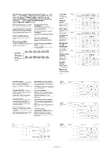
1. All Keys Operation Check
Connection Method :
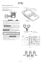
1) While pressing the P key and the
Á
+ k e y ,
ture ON the main power of the regulated power supply (DC
+6V). (Refer to Fig. 1-1.)
2) Remove all hands from pressing the all keys described in above
step 1). The all indications of the LCD must be turned OFF.
(Refer to Fig. 1-2.)
3) When any key of the Operation panel-key block (except
the COMMANDER OFF key), or any key of the LCD touch-
key block is pressed, the signal (carrier 40kHz) as shown in
Fig. 1-3 must be transmitted in accordance the pressed key, when
operation of the machine is normal.
4) Press all keys of the Operation panel-key block (except the
COMMANDER OFF key, and of the LCD touch-key block
sequentially. When all keys are pressed, confirm that the long
buzzar sound and all LCD displays are turned off.
NOTE
: Be careful that all data in S-RAM is cleared
when the above TEST mode is performed.
•
This TEST Mode can be terminated in its middle before testing
all keys by pressing the COMMANDER OFF key. However
the conduction check of the remairing keys cannot be checked.
(S-RAM is not cleared.)
•
P-ROM (IC8) is diagnosed to be free from defects when the
steps from 1) to 4) are performed correctly.
+
–
Regulated power supply
(+6V constant voltage output)
set
+6V pin
LCD touch-key block
COMMANDER OFF
P
Á
+
Operation
panel-key block
+
+
PROGRAM
Turn ON the
main power (DC 6V)
While pressing both keys
at the same time;
Á
2.4mscc
2.4mscc
2.4mscc
600
µ
sec
600
µ
sec
Fig. 1-1
Fig. 1-2
Fig. 1-3
(See Fig. 3-1.)
Summary of Contents for RM-AV2000T
Page 3: ... 3 SECTION 1 GENERAL This section is extracted from instruction manual ...
Page 4: ... 4 ...
Page 5: ... 5 ...
Page 6: ... 6 ...
Page 7: ... 7 ...
Page 8: ... 8 ...
Page 9: ... 9 ...
Page 10: ... 10 ...
Page 11: ... 11 ...
Page 12: ... 12 ...
Page 13: ... 13 ...
Page 14: ... 14 ...

