2-1(E)
RM-B150
2-1. Removing the Cabinet
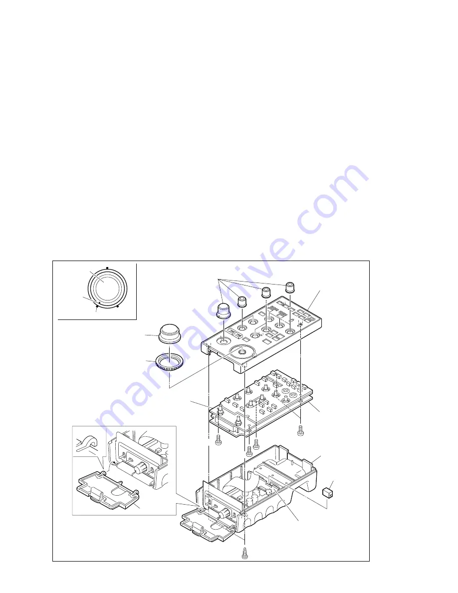
Opening the Remote Control Unit
Loosen the two screws (BTP2.6
x
10) in the bottom of the unit.
n
Before closing, fit the ROM holder onto the CN-1651 board without fail. Use of the ROM holder pre-
vents the ROM on the CPU-266 board from coming off.
Removing the CPU-266/SW-962 boards from the control panel assembly
Remove the nine knobs and iris ring. Remove the five screws (B2.6
x
4) securing the boards to the control
panel assembly.
n
When fitting the knob, first turn the shaft of the adjustment control fully counterclockwise and fit the
knob so that the notch on the knob is in proper alignment with indexes on the control panel as shown in
the figure
1
.
Reinstalling the MENU lid
The MENU lid may come off due to impact. It can be reinstalled easily as shown in the figure
2
.
Section 2
Service Overview
B2.6
x
4
B2.6
x
4
BTP2.6
x
10
MENU lid
B2.6
x
4
Knob
Notch
Index
Fig.
1
Knob
Knobs
Iris ring
Control panel
assembly
Fig.
2
SW-962 board
ROM holder
CN-1651 board
Bottom chassis
CPU-266 board


