3-1(E)
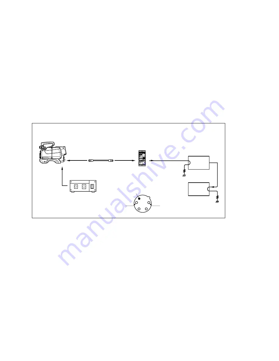
RM-B150
PIX
75
A-ch
75
Z
Z
DC IN
MONITOR
REMOTE
CONTROL UNIT
RM-B150
COLOR VIDEO CAMERA
1
4
2
3
+
_
*
*
REMOTE
BVP-950/550 series
CAMERA ADAPTOR
CA-570/530 series
CCD UNIT
OHB series
Color monitor
Waveform monitor/
Vector scope
AC ADAPTOR
AC-550/550CE
or DC variable power supply
REMOTE CABLE
(supplied with RM-B150,10 m)
Micro switch
3-1. Preparation
Measuring Equipment
.
Waveform monitor/Vectorscope
Tektronix 1780R (for NTSC)/1781R (for PAL) or equivalent
.
Color monitor
Peripheral Equipment
.
BVP-550/550P
+
CA-530/570 series
+
OHB-450/550 series, or
BVP-950/950P
+
CA-530/550/570 series
+
OHB-730/750A series
.
AC adaptor AC-550/550CE, or DC variable power supply
Connection
If using a DC variable power supply to drive power, connect the positive (
+
) side of the power supply to
pin 4 of the DC IN connector on the camera adaptor, and negative (
_
) side to pin 1.
n
When the power is supplied via the DC IN connector, be sure to press the micro switch on the DC IN
connector, that turns on the power. It is recommended to use an XLR plug when driving power via the
DC IN connector.
Initial settings
.
ACTIVE button/Control panel:
ON (lit)
.
OUTPUT switch/Control panel:
BARS
.
DISPLAY switch/Menu panel:
OFF
.
CABLE COMP SELECT
*
1
:
10 m
*
1: To select the cable length, use the menu of this unit. For details, refer to the operation manual supplied with the unit.
Section 3
Electrical Alignment


