1-10 (E)
RM-B750
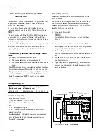
MONITOR
FUNCTION
VF DISP
MAINTENANCE
VF MENU
SCENE
CANCEL
PAINT
ENTER
ALARM
PANEL
ACTIVE
MEMORY
STICK
STANDARD
TEST
BARS
CLOSE
AWB
AUTO
IRIS
IRIS/MB
ACTIVE MASTER
BLACK
REMOTE CONTROL UNIT RM-B750
EXT
IRIS
WHITE
BLACK
ABB
VTR
START/STOP
PANEL ACTIVE
button
FUNCTION button
MAINTENANCE button
SCENE button
STANDARD button
MENU SELECT
BRIGHT
CONTRAST
Data write procedure
Data write procedure in the PLD (or ROM for PLD) is
outlined below.
For details of data write procedure, refer to “Download
Tool Operating Instruction for Device Programming”
which is available in the same site where the PLD Down-
load Tool software is available.
1.
Prepare the Project file.
n
Download the Project file from the Sony Database
Server.
2.
Turn off the power of this unit. Connect the PC
parallel port to the EPR connector of the target board
using the PLD download fixture (cable).
3.
Turn on the power of this unit.
Start the Download Tool software and read the Project
file.
4.
Program the PLD (or ROM for PLD) with the Down-
load Tool software.
5.
Upon completion of programming, check that error
message is not displayed. Turn off the power of this
unit and back on.
1-10. Note on Service
1-10-3. Writing and Rewriting the PLD
Internal Data
This unit uses the PLD (Programmable Logic Device) that
supports the e-Production (EPR) system to write and
rewrite the internal data.
If the part listed below needs to be replaced or to be
upgraded, contact your Sony Sales Office/Service Center.
n
The part number of PLD (or ROM for PLD) in which data
is not written yet, is shown in “Section 3. Spare Parts”.
Therefore, if part replacement is required, write the data by
the following procedure.
In the case of the PLD type that runs on the program stored
in external ROM, data needs not to be written only by
replacing the part if the specific PLD only is defective.
e-Production system has the advantages shown
below.
.
To write/rewrite the PLD internal data:
1.
The standard fixture (cable) can be used.
2.
The standard software (PLD Download Tool) can be
used.
.
The PLD internal data is controlled in the Sony Database
Server under the name Project file (E_xxx_xxx_xx_xx).
.
The printed circuit board is equipped with the standard
connector (EPR connector) to write the PLD internal
data. The indication “EPR” is shown on the printed
circuit board.
Corresponding PLD
PLD
EPR connector
Project file No.
(Ref No./board name) (Ref No./board name)
IC106/MPU-124
CN101/ MPU-124
E_000_000_31_xx
Equipment required
.
PLD download fixture
(Sony part number: J-7120-140-A)
The cable connected PC to this unit.
.
PC
A PC having parallel port.
A PC in which the PLD Download Tool software is
already installed.
For the applicable OS and the operating environment,
refer to “Download Tool Operating Instruction for
Device Programming”.


