1 (E)
RM-B750
Table of Contents
Manual Structure
Purpose of this manual ........................................................................................ 3 (E)
Relative manuals ................................................................................................. 3 (E)
Contents ............................................................................................................... 4 (E)
1. Service Overview
1-1.
Connector Input/Output Signals ............................................................ 1-1 (E)
1-2.
Connection Connector/Cable ................................................................ 1-1 (E)
1-3.
Opening the RM-B750 .......................................................................... 1-1 (E)
1-4.
Board Layouts ....................................................................................... 1-2 (E)
1-5.
Functions of Internal Switches .............................................................. 1-2 (E)
1-6.
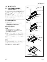
Flexible Card Wire ................................................................................ 1-3 (E)
1-6-1.
Disconnecting/Connecting the Flexible Card Wire ............. 1-3 (E)
1-6-2.
Shaping the Flexible Card Wire ........................................... 1-4 (E)
1-7.
Replacing the LCD Unit ........................................................................ 1-5 (E)
1-8.
Replacing the Touch Panel and Backlight ............................................ 1-7 (E)
1-9.
Installing the IRIS Knob Assembly and WHITE Knob Assembly ....... 1-8 (E)
1-9-1.
Installing the IRIS Knob Assembly ..................................... 1-8 (E)
1-9-2.
Installing the WHITE Knob Assembly ................................ 1-9 (E)
1-10. Note on Service ..................................................................................... 1-9 (E)
1-10-1. Information of the Software Version ................................... 1-9 (E)
1-10-2. Description on Backup Battery ............................................ 1-9 (E)
1-10-3. Writing and Rewriting the PLD Internal Data ................... 1-10 (E)
1-10-4. Note on Replacing the FRAM ............................................ 1-11 (E)
1-10-5. Checking the Software Version ......................................... 1-11 (E)
1-10-6. Updating the Software ........................................................ 1-11 (E)
1-10-7. Touch Panel Calibration ..................................................... 1-12 (E)
1-10-8. Diagnosis ............................................................................ 1-13 (E)
1-10-9. Circuit Protective Elements ................................................ 1-14 (E)
1-10-10. Unleaded Solder ................................................................. 1-14 (E)
1-11. Recommended Replacement Parts ...................................................... 1-15 (E)
2. Electrical Alignment
2-1.
Preparation ............................................................................................ 2-1 (E)
2-2.
Adjusting the Video Level .................................................................... 2-2 (E)


