4 (E)
RM-B750
Contents
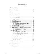
The following are summaries of the each section for understanding the manual.
Section 1
Service Overview
Describes information about connector input/output signals, function of internal
switches board locations, replacement of part and notes on services.
Section 2
Electrical Alignment
Describe video level adjustment procedure.
Section 3
Spare Parts
Describes parts list, exploded views and frame list used in the unit.
Section 4
Semiconductor Pin Assignments
Contains information on semiconductors used for the unit.
It includes a complete list of the semiconductors and their ID Nos. for retrieving
information on “Semiconductor Pin Assignments” CD-ROM, which is available
separately.
Please refer to this section together with the “Semiconductor Pin Assignments”
CD-ROM.
Information on the semiconductors not contained in the CD-ROM at the time of
issue of this manual, if any, is given in this section as well.
Section 5
Block Diagram
Describe overall block diagram.
Section 6
Schematic Diagrams
Describes schematic diagrams for every circuit board and frame wiring.
Section 7
Board Layouts
Describes board layouts for every circuit board.


