background image

19

Note

The same IP address as a remote controller 

cannot be set.

The subnet mask (SM) and gateway address 

(GW) of the camera are assigned the same 

settings as the remote controller.

The DHCP setting of the camera is set to Off.

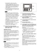
Turn the SELECT knob to move the 

cursor to IP under [FROM].

Set the start value of the IP addresses 

to assign to newly registered cameras.

Turn the SELECT knob clockwise to move 

the cursor to the first three digits (for 

example, 192).
















Turn the VALUE knob to set the value.

Turning clockwise increases the value, 

and turning counterclockwise decreases 

the value.

Turn the SELECT knob to move to the 

next number and repeat step 

 to set 

the other numbers.

Turn the SELECT knob to move the 

cursor to IP under [TO].

Set the end value of the IP addresses to 

assign to newly registered cameras.

Turn the SELECT knob clockwise to move 

the cursor to the first three digits (for 

example, 192).













Turn the VALUE knob to set the value.

Turning clockwise increases the value, 

and turning counterclockwise decreases 

the value.

Turn the SELECT knob to move to the 

next number and repeat step 

 to set 

the other numbers.

When finished making all settings, turn 

the SELECT knob to move the cursor to 

SETUP IP.

Turn the VALUE knob to change NOT 

EXEC to EXEC, then press the VALUE 

button.

A “WAIT FOR A FEW SECONDS” message 

is displayed on the screen.

When the message disappears, turn 

the VALUE knob to change NO to YES, 

then press the VALUE button.

Check the camera assignment result 

using AUTO IP SETUP >CAMERA TABLE 

in the RM menu.

For details about displaying CAMERA 

TABLE, see “To check the camera table” 

(page 21).

Assignment using AUTO IP SETUP >ASSIGN 

CAM

This method is used to assign camera 

numbers to cameras that already have a 

configured IP address.

With this method, you can specify the group 

number and camera number of the camera 

selection button from which to start 

assignments.

Camera assignments are made in ascending 

IP address order.

For details about the group number and 

camera number, see “Selecting a Camera” 

(page 34).

Note

Only cameras within the same segment can 

be assigned.

Turn the SELECT knob to move the 

cursor to GROUP NUM.

Set the group number for which to begin 

assignment.

Turn the VALUE knob to set the value.

Turning clockwise increases the value, 

and turning counterclockwise decreases 

the value.

Turn the SELECT knob to move the 

cursor to CAMERA NUM.

Set the camera number for which to 

begin assignment.

Summary of Contents for RM-IP500

Page 1: ...emote Controller Operating Instructions Before operating the unit please read this manual thoroughly and retain it for future reference RM IP500 Software Version 2 2 4 696 257 14 1 2017 Sony Corporation ...

Page 2: ...eo to a Memory Card ILME FR7 44 Storing the Camera Status Preset Function 45 Recalling stored status 46 Changing the speed of movement between positions 46 Recording the Pan Tilt Zoom Operation of a Camera Trace Function 47 Recording the pan tilt zoom operation 47 Starting playback of a recorded trace 47 Operating the Camera Setup Menu from the Unit Camera Menu Operation Mode excluding ILME FR7 48...

Page 3: ...r countries Google Chrome is a trademark or registered trademark of Google LLC Wi Fi is a registered trademark of Wi Fi Alliance All other company and product names are trademarks or registered trademarks of the respective companies or their respective makers Trademarked items are not indicated by or symbols in this manual Data and security SONY WILL NOT BE LIABLE FOR DAMAGES OF ANY KIND RESULTING...

Page 4: ...onality and operability of Sony PTZ cameras Simple system construction The unit can be used to control up to 100 cameras connected via LAN connection using switching hubs You can build a system using the setup functions of the unit to set the IP address and camera number of multiple cameras in a single step without using a setup PC Functional design The buttons and knobs of the control panel are g...

Page 5: ...Color adjustment block Use to perform color adjustments on a camera Select the target camera to adjust the color The color adjustment block is enabled when the ACTIVE button is lit For details about selecting the target camera see Selecting a Camera page 34 Color adjustment block page 5 Menu control block page 6 Camera selection block page 7 Lens control block page 8 Preset memory control block pa...

Page 6: ...xecutes one push auto white balance adjustment on the target camera For details see To adjust the white balance automatically page 40 O P ABB one push auto black balance button excluding ILME FR7 Executes one push auto black balance adjustment on the target camera For details see To adjust the black balance automatically page 40 REC START STOP button ILME FR7 Starts stops recording video to the me...

Page 7: ...a higher level in the hierarchy for menu items that have a multi level hierarchy RM MENU button Press this button to display the setup menu of the unit on the LCD panel For details about menu operations see Menu Operations page 12 CAM MENU button Press and hold this button to display the setup menu of the camera on the monitor output of the camera Nothing is displayed on the LCD panel of the unit ...

Page 8: ...or details see To control the zoom using the ZOOM lever on the lens control block page 37 ACTIVE button Enables disables the lens control block When the button is pressed turning it on button is lit the lens control block becomes enabled When the button is turned off button is not lit the lens control block becomes disabled except for the ZOOM SPEED knob operation FOCUS SPEED knob Sets the focus s...

Page 9: ...y control block When the button is turned on button is lit the preset memory control block becomes enabled When the button is turned off button is not lit the preset memory control block becomes disabled STORE button Stores the camera status in the internal memory of the camera for the specified preset number For details see Storing the Camera Status Preset Function page 45 RECALL button Recalls a...

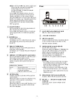
Page 10: ... operation of the joystick control block When the button is turned on button is lit operation of the joystick control block becomes enabled When the button is turned off button is not lit operation of the joystick control block becomes disabled Rear Anti theft wire attachment point Attach a wire to prevent theft Ground connection GPI I O connector Used as a tally input from an external device or a...

Page 11: ...oles on the front left and right sides protected by covers six locations Side front Screw hole protective covers When mounting the unit on other than a flat surface remove the screw hole protective covers and secure the unit in place with screws There are a total of six covers on the front left and right sides Notes Use standard size screws with the following dimensions Do not overtighten the scre...

Page 12: ...figure picture quality adjustments and compensation functions on target cameras configure the unit execute configure auto assign functions on cameras and for performing configuration from a connected setup PC When the RM MENU button is turned on RM menu setup mode is invoked and the top menu is displayed on the LCD panel For details see RM Menu List page 68 Camera menu Turns the superimposed outpu...

Page 13: ...or moves up down as the SELECT knob is turned 3 Press the SELECT button The menu for the selected item appears 4 Turn the SELECT knob to move the cursor to the desired setup menu item The cursor moves up down as the SELECT knob is turned 5 Press the SELECT button The selected menu item and its setup items appear Operation Buttons and knobs used OPERATION menu CONFIG AUTO IP SETUP or MAINTENANCE me...

Page 14: ... select the setting For items that require confirmation after the setting is changed the current selection is displayed highlighted Press the VALUE button to apply the change The highlight display disappears To configure items in other menus Press the CANCEL button to return to the parent item in the menu and then use the same procedure Cursor ...

Page 15: ...rating instructions for each camera VISCA over IP LAN connection VISCA over IP LAN connection is configured using the following sequence Setting the IP address of the unit Before connection set the IP address of the unit The setting is configured using CONFIG LAN in the RM menu 1 Press the RM MENU button turning it on button is lit yellow The RM menu top menu appears 2 Turn the SELECT knob to move...

Page 16: ...lue Turning clockwise increases the value and turning counterclockwise decreases the value Turn the SELECT knob to move to the next number and repeat step to set the other numbers 7 Set SM subnet mask and GW default gateway address in the same way as described in steps 5 and 6 8 When finished making all settings move the cursor to APPLY 9 Turn the VALUE knob to change NOT EXEC to EXEC then press t...

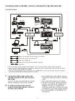
Page 17: ...delay may cause a malfunction Use a high quality network Do not mix 10BASE T and 100BASE TX in the network RM IP500 BRC H900 BRBK IP10 IP control card 3 RM IP10 Switching hub BRC X1000 BRC H800 Video switcher 1 SRG 360SHE Setup PC Video monitor Remote control signal LAN cable category 5 or higher Tally contact signal Connection cable 2 Video signal HDMI cable Video signal Connection cable with BNC...

Page 18: ...uttons and CAMERA number buttons of the camera selection block Camera assignments are performed using AUTO IP SETUP SETUP IP or AUTO IP SETUP ASSIGN CAM in the RM menu Notes Only cameras that are on the same segment as the remote controller can be assigned using AUTO IP SETUP Use the setup software to assign cameras on different segments For an ILME FR7 run AUTO IP SETUP within 20 minutes of start...

Page 19: ...numbers When finished making all settings turn the SELECT knob to move the cursor to SETUP IP Turn the VALUE knob to change NOT EXEC to EXEC then press the VALUE button A WAIT FOR A FEW SECONDS message is displayed on the screen When the message disappears turn the VALUE knob to change NO to YES then press the VALUE button Check the camera assignment result using AUTO IP SETUP CAMERA TABLE in the ...

Page 20: ... the SELECT knob to move the cursor to AUTO IP SETUP 3 Press the SELECT button The AUTO IP SETUP menu appears 4 Turn the SELECT knob to select CLEAR TABLE and press the SELECT button The CLEAR TABLE menu appears 5 Turn the VALUE knob to change NOT EXEC to EXEC then press the VALUE button 6 Turn the VALUE knob to change NO to YES then press the VALUE button To swap camera numbers You can change the...

Page 21: ...ber and the camera number of the camera to change To change the registration Turn the SELECT knob to move the cursor to CAMERA under CHANGE Turn the VALUE knob to select the camera group number and the camera number of the camera assignment to change to To clear the registration Turn the SELECT knob to move the cursor to CHANGE Turn the VALUE knob to change CHANGE to CLEAR 6 Turn the SELECT knob t...

Page 22: ...to 10 in a group are displayed when UPPER is selected LOWER display UPPER display You can turn the SELECT knob to move the cursor to CAM INFO then turn the VALUE knob to switch the camera information between IP ADD and MAC ADD display In IP ADD display the IP addresses of the cameras are displayed In MAC ADD display the MAC addresses of the cameras are displayed MAC address display LOWER or UPPER ...

Page 23: ...erial connection only one SRG 360SHE camera can be connected to a single remote controller To connect multiple SRG 360SHE cameras or to mix with other model cameras use the connection described in VISCA over IP LAN connection page 15 The ILME FR7 does not support serial connection RM IP500 Camera with RJ 45 connector Up to seven cameras RM IP500 Camerawith RJ 45connector Camera with RJ 45 connecto...

Page 24: ... 6 7 8 TXD_IN TXD_IN GND GND RXD_IN NC NC 1 2 3 4 5 6 7 8 RXD_OUT RXD_OUT TXD_OUT GND GND TXD_OUT NC NC RXD_IN 3rd to 7th camera Camera with RJ 45 connector 2nd camera Camera with RJ 45 connector VISCA RS 422 IN connector RJ 45 RM IP500 Remote Controller VISCA RS 422 OUT connector RJ 45 VISCA RS 422 IN connector RJ 45 1st camera Camera with 9 pin connector VISCA RS 422 connector connector block NC...

Page 25: ...knob to move the cursor to SERIAL and press the SELECT button The SERIAL menu appears Set the baud rate as required Turn the SELECT knob to move the cursor to BAUD RATE turn the VALUE knob and select 9600 or 38400 The default setting is 9600 5 Turn the SELECT knob to move the cursor to APPLY 6 Turn the VALUE knob to change NOT EXEC to EXEC then press the VALUE button The following message appears ...

Page 26: ...nection with an MCX 500 Multi Camera Live Producer as an example Connection example BRC X1000 BRC H800 SRG 360SHE BRC H900 Video signal Video signal Video signal MCX 500 Multi Camera Live Producer To video monitor Tally signal RM IP500 Tally contact signal Connection cable 1 Video signal HDMI cable Video signal Connection cable with BNC connectors 1 Use a connection cable designed for the switcher...

Page 27: ...ignal Connection cable 1 Video signal Connection cable with BNC connectors or HDMI cable Signal flow Wi Fi router Video switcher Web app 1 Use a connection cable designed for the switcher being used For the specifications of the GPI I O connector of the unit see Pin assignments page 83 Switching hub Tablet To video monitor RM IP500 ILME FR7 SDI or HDMI LAN ILME FR7 SDI or HDMI LAN ...

Page 28: ...it on button is lit yellow The RM menu top menu appears 2 Turn the SELECT knob to move the cursor to MAINTENANCE 3 Press the SELECT button The MAINTENANCE menu appears 4 Turn the SELECT knob to move the cursor to UPDATE MODE 5 Press the SELECT button The UPDATE MODE setup screen appears 6 Turn the VALUE knob to change OFF to ON then press the VALUE button The buttons and LED indicators start blink...

Page 29: ...utton The file selection dialog appears 3 Select the saved controller configuration data 4 Click the Restore button on the Backup Restore screen The restore process starts When the configuration data is restored the following message appears and then the remote controller reboots Updating the firmware 1 Download the firmware update from the download site 2 Uncompress the downloaded compressed file...

Page 30: ...re the following IP address settings Camera assignments Swapping camera numbers Checking camera tables Install the software on the setup PC for the unit The setup tool software and setup tool guide can be downloaded from the download site For details refer to the RM IP Setup Tool guide Note To use the RM IP Setup Tool set MAINTENANCE UPDATE MODE to ON in the RM menu ...

Page 31: ... buttons and knobs shown in the thick frames are marked with the function name for an ILME FR7 Note If you already use this unit you can purchase the panel sheet separately For details consult with your Sony dealer To use the panel sheet adhesively attached to the panel surface attach the panel sheet using the following procedure 1 Remove any dirt from the panel surface Clean the surface using a c...

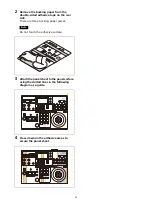
Page 32: ...tape on the rear side There are three backing paper pieces Note Do not touch the adhesive surface 3 Attach the panel sheet to the panel surface using the dotted lines in the following diagram as a guide 4 Press down on the adhesive areas to secure the panel sheet ...

Page 33: ...vices Notes Be sure to turn on the power of the cameras before the power of this unit Do not touch the joystick or ZOOM lever when turning on the power of the unit Touching the joystick or ZOOM lever will prevent the center point position check from operating correctly when power is applied To turn the unit off To turn the unit off to change connection or perform maintenance use the reverse proced...

Page 34: ...ow and the camera assigned with the same camera number as the CAMERA button becomes the target camera For serial connection camera numbers up to number 7 can be assigned In a serial connection groups are not used hence the group buttons do not light up About the color of camera buttons The camera number button for the selected camera is lit yellow When a camera is turned on or is in standby mode t...

Page 35: ...is not lit If it is lit press the press the button to turn it off 4 Operate the joystick to pan or tilt the camera While checking the picture on the screen incline the joystick in the desired direction The panning tilting speed changes according to the angle at which you incline the joystick Return the joystick to the center position to stop pan tilt operation To adjust the pan tilt speed You can ...

Page 36: ...ing the picture on a screen you can change the direction the camera moves using CONFIG DIRECTION in the RM menu For details about configuration see DIRECTION page 74 Note The setting above only changes the control signal from the unit and does not change the setting of the camera itself Zoom control The camera zoom can be operated using either the ZOOM ring on the top of the joystick or the ZOOM l...

Page 37: ...et camera to control For details about selection see Selecting a Camera page 34 2 Press the ACTIVE button turning it on button is lit on the lens control block 3 Move the ZOOM lever left right Moving the lever to the left makes the subject appear smaller Wide angle Moving the lever to the right makes the subject appear larger Telephoto The zoom speed changes depending on the pressure applied to th...

Page 38: ...the knob clockwise increases the focus speed and turning counterclockwise decreases the focus speed One push auto focus during manual focus adjustment Press the O P A F one push auto focus button The button blinks yellow for a few seconds and then the camera focuses on the subject in the center of the screen automatically Adjusting the brightness 1 Select the target camera to control For details a...

Page 39: ... turning it off button is not lit Note On the BRC H900 to turn the AE button off also turn this function off Flicker compensation FLICKER Use the following procedure if there is any flicker in the image of the subject due to the effects of fluorescent lighting or other light sources For details about function assignments to assign buttons see Assigning Functions to Assign Buttons page 51 1 Select ...

Page 40: ...s changed significantly Note Check that OPERATION BLACK ABB MODE is set to ON in the RM menu The black balance function cannot be executed if ABB MODE is set to OFF 1 Select the target camera to control For details about selection see Selecting a Camera page 34 2 Press the ACTIVE button turning it on button is lit on the color adjustment block 3 Adjust the black balance automatically or manually T...

Page 41: ... the FOCUS knob The focus speed is set using the FOCUS SPEED knob While the Push AF MF button is pressed auto focus operates push auto focus AF AF S Tip You can perform more accurate operation using the Web App of the camera For details refer to the Help Guide of the camera Adjusting the brightness 1 Select the target camera to control For details about selection see Selecting a Camera page 34 2 P...

Page 42: ... SELECT button The CONFIG menu appears 3 Turn the SELECT knob to move the cursor to SW ASSIGN and press the SELECT button The assign button setup menu appears 4 Turn the SELECT knob to move the cursor to IRIS KNOB 5 Turn the VALUE knob to select ND CLEAR or ND FILTER and press the VALUE knob When ND CLEAR is selected turning the knob quickly in the direction to increase the brightness beyond ND1 4...

Page 43: ...t ATW operation and Offset White refer to the Help Guide of the camera Note Before using ATW check the setting for Offset White ATW in the camera menu It is recommended that all settings be set back to 0 after use To adjust the white balance automatically auto white balance Position a white object under the same lighting conditions as the subject you want to shoot and zoom in on it on the screen Y...

Page 44: ... for recording refer to the Help Guide of the camera 2 Press the REC START STOP button in the color adjustment block of the unit The camera starts recording and the button lights up red To stop recording press the REC START STOP button again Recording stops and the button turns off not lit To play back the memory card video 1 Set each of Thumbnail and Slot Select to one of the assignable buttons A...

Page 45: ...tions for memory preset operation using OPERATION OTHER PRST SPEED in the RM menu This setting is applied to all presets The speed of movement default setting is 24 The number of presets varies depending on the camera For details refer to the specifications for the camera 1 Press the ACTIVE button turning it on button is lit on the joystick control block and preset memory control block 2 Select th...

Page 46: ...gistering a preset we recommend that you check that the camera status is stored correctly by recalling the preset Recalling stored status There are two methods for recalling stored status direct recall and number recall Pressing and holding the CLEAR button cancels the recall operation and stops the camera at its current position Direct recall With the DIRECT RECALL button on button is lit yellow ...

Page 47: ...k to pan tilt the orientation of the camera 4 Check that the DIRECT RECALL button is off If the button is on button lit yellow turn it off button not lit 5 Enter the preset number you want to store Use the PRESET 10 0 button to enter a 0 digit The maximum number that can be saved varies depending on the camera The preset number is displayed at the bottom right on the LCD panel of the menu control ...

Page 48: ...MODE settings see page 34 and page 75 Operating the Camera Setup Menu from the Unit Camera Menu Operation Mode excluding ILME FR7 You can operate the setup menu on the camera using the knobs and buttons on the menu control block and the joystick Notes In camera menu operation mode the menu is displayed on the monitor output of the camera Nothing is displayed on the LCD panel of the unit Operation ...

Page 49: ...button to confirm the selection of menu items If a menu item has sub items those sub items are displayed VALUE knob Selects settings The setting changes as the VALUE knob is turned counterclockwise clockwise CANCEL button Press this button to go back one level in the menu and to exit the setup menu Note On the SRG series and BRC X400 X401 pressing the CANCEL button during menu operation will exit ...

Page 50: ...oystick The operation of the a joystick button is the apply operation SET button operation defined by the camera 4 When finished press the CAM GUI P T RST button turning it off button is not lit The joystick operation returns to pan tilt operation To operate the camera menu To show hide the camera menu press and hold the CAM MENU button When two or more of the IRIS button ISO GAIN button and SHUTT...

Page 51: ...t value and selection options see To operate the ND filter using the IRIS knob page 42 Use the following procedure to assign a function 1 Press the RM MENU button turning it on button is lit yellow The RM menu top menu appears 2 Turn the SELECT knob to move the cursor to CONFIG and press the SELECT button The CONFIG menu appears 3 Turn the SELECT knob to move the cursor to SW ASSIGN and press the ...

Page 52: ...GN 3 ASSIGN 4 ASSIGN 5 ASSIGN 6 ASSIGN1 ASSIGN2 ASSIGN3 ASSIGN4 ASSIGN5 ASSIGN6 ASSIGN7 ASSIGN8 ASSIGN9 FOCUS HOLD Direct Menu Focus Setting Rec Review Push Auto ND Crop Select Marker Video Signal Monitor Clip Flag OK Color Bars Focus Hold ASSIGN button functions of the unit ASSIGN 1 Crop Select ASSIGN 2 Focus Setting ASSIGN 3 Rec Review ASSIGN 4 Push Auto ND ASSIGN 5 Video Signal Monitor ASSIGN 6...

Page 53: ...orehand The following sections describe example recommended settings Button knob Function assignment menu item 1 OPERATION WHITE WB MODE 2 CONFIG RM SETUP AE CONFIG2 3 CONFIG SW ASSIGN ASSIGN1 CONFIG SW ASSIGN ASSIGN2 CONFIG SW ASSIGN ASSIGN3 4 CONFIG SW ASSIGN ASSIGN4 CONFIG SW ASSIGN ASSIGN5 CONFIG SW ASSIGN ASSIGN6 5 CONFIG SW ASSIGN IRIS KNOB 1 3 4 5 2 ...

Page 54: ...IG SW ASSIGN ASSIGN1 DISPLAY CONFIG SW ASSIGN ASSIGN2 ASSIGN 4 Push Auto ND CONFIG SW ASSIGN ASSIGN3 ASSIGN 9 ND Filter Position CONFIG SW ASSIGN ASSIGN4 ND FILTER CONFIG SW ASSIGN ASSIGN5 AUDIO LVL CONFIG SW ASSIGN ASSIGN6 AE LEVEL CONFIG SW ASSIGN IRIS KNOB IRIS The orange labels indicate the buttons knobs used and their assigned functions All uppercase functions can be assigned directly on this...

Page 55: ... ASSIGN1 DISPLAY CONFIG SW ASSIGN ASSIGN2 ASSIGN 7 Video Signal Monitor CONFIG SW ASSIGN ASSIGN3 ASSIGN 9 ND Filter Position CONFIG SW ASSIGN ASSIGN4 ND FILTER CONFIG SW ASSIGN ASSIGN5 ASSIGN 6 Base ISO Sensitivity CONFIG SW ASSIGN ASSIGN6 AUDIO LVL CONFIG SW ASSIGN IRIS KNOB ND FILTER The orange labels indicate the buttons knobs used and their assigned functions All uppercase functions can be ass...

Page 56: ...Base ISO Sensitivity CONFIG SW ASSIGN ASSIGN3 ASSIGN 9 ND Filter Position CONFIG SW ASSIGN ASSIGN4 ASSIGN 7 Video Signal Monitor CONFIG SW ASSIGN ASSIGN5 AUDIO LVL CONFIG SW ASSIGN ASSIGN6 AE LEVEL CONFIG SW ASSIGN IRIS KNOB ND FILTER Auto ND Filter Auto Iris AGC Auto Shutter The orange labels indicate the buttons knobs used and their assigned functions All uppercase functions can be assigned dire...

Page 57: ... FILTER CONFIG SW ASSIGN ASSIGN1 DISPLAY CONFIG SW ASSIGN ASSIGN2 ASSIGN 9 LUT On Off CONFIG SW ASSIGN ASSIGN3 ASSIGN 7 Video Signal Monitor CONFIG SW ASSIGN ASSIGN4 ND FILTER CONFIG SW ASSIGN ASSIGN5 ASSIGN 6 Base ISO Sensitivity CONFIG SW ASSIGN ASSIGN6 AUDIO LVL CONFIG SW ASSIGN IRIS KNOB ND FILTER The orange labels indicate the buttons knobs used and their assigned functions All uppercase func...

Page 58: ...P AE CONFIG2 ND IRIS CONFIG SW ASSIGN ASSIGN1 DISPLAY CONFIG SW ASSIGN ASSIGN2 ASSIGN 6 Marker CONFIG SW ASSIGN ASSIGN3 ASSIGN 7 Video Signal Monitor CONFIG SW ASSIGN ASSIGN4 ND FILTER CONFIG SW ASSIGN ASSIGN5 DETAIL CONFIG SW ASSIGN ASSIGN6 AE LEVEL CONFIG SW ASSIGN IRIS KNOB IRIS The orange labels indicate the buttons knobs used and their assigned functions All uppercase functions can be assigne...

Page 59: ...ANUAL IRIS Pri GAIN Pri or SHUTTER Pri in the RM menu For details about AE CONFIG see AE CONFIG page 73 2 Press the AE button turning it off button is not lit The IRIS GAIN or SHUTTER button operation which is enabled lit blue is determined by the AE CONFIG setting 3 Press the IRIS GAIN or SHUTTER button The button is lit yellow and the adjustment item and setting are displayed on the LCD panel 4 ...

Page 60: ...he VALUE knob FUNCTION menu or multi function dial mode This allows you to set some functions more quickly than by using normal menu operations Note To use functions displayed on the camera image set the camera to superimpose the screen display on the image output used for operating this unit 1 Picture profile is not supported on the ILME FR7 Target buttons functions LCD display Setting display de...

Page 61: ...he SELECT knob and button or the VALUE knob and button multi function dial mode When the camera menu is not displayed press the SELECT button or VALUE button to activate direct menu operation on the shooting screen For details about direct menu operation refer to the Help Guide of the camera Notes Function buttons are disabled during camera menu display First exit the camera menu In cases such as ...

Page 62: ...r changes from to when the camera zoom is in that range Restoring Factory Default Settings You can restore all settings stored in the unit to their factory default values This operation is performed using MAINTENANCE RESET in the RM menu 1 Press the RM MENU button turning it on button is lit yellow The RM menu top menu appears 2 Turn the SELECT knob to move the cursor to MAINTENANCE 3 Press the SE...

Page 63: ...in the following table 1 ILME FR7 only When MEM A is selected on the camera the WHITE knob adjusts the color temperature and tint respectively 2 Default value of 50 for models sold in China Menu item Sub menu item Setup item Default value OPERATION WHITE WB MODE MEM A T T 1 OTHER PRST SPEED 24 CONFIG RM SETUP AE CONFIG MANUAL AE CONFIG2 ALL CAM POWER EACH ZOOM LEVER CAMERA FREQ 59 94 2 LCD BRIGHT ...

Page 64: ... menu Yes Yes Yes Color adjustment block O P AWB one push auto white balance button One push white balance auto adjustment Enabled when OPERATION WHITE WB MODE is set to ONE PUSH in the RM menu Yes Yes Yes O P ABB one push auto black balance button One push black balance auto adjustment Enabled when OPERATION BLACK ABB MODE is set to ON in the RM menu Yes BARS button Toggle color bars output on of...

Page 65: ...yed Enabled when OPERATION EXPOSURE EX COMP is set to ON in the RM menu ND1 to ND 4 ND filter settings Yes 8 PP1 to PP6 picture profile settings Yes 12 IRIS button lit blue when enabled IRIS setting display Enabled when the AE button is not lit Yes Yes Yes Adjustment using VALUE knob after IRIS setting is displayed Enabled when the AE button is not lit and CONFIG RM SETUP AE CONFIG is set to MANUA...

Page 66: ...b Manual focus adjustment AF MF button Focus adjustment mode selection Push AF MF button Temporary focus adjustment mode change When the AF MF button is on lit Auto focus stops while the button is pressed When the AF MF button is off not lit Auto focus operates while the button is pressed ND FILTER IRIS knob Iris value or ND filter value adjustment Iris value adjustment when CONFIG SW ASSIGN IRIS ...

Page 67: ...nd KNEE MODE is set to MANUAL in the camera menu Direct menu AE Mode Level shortcut button Enabled on the shooting screen Operated using the VALUE knob Direct menu ND filter shortcut button Enabled on the shooting screen Operated using the VALUE knob Audio input level setting Camera assignable buttons 1 to 9 FOCUS HOLD lens assignable button IRIS button Direct menu IRIS shortcut button Enabled on ...

Page 68: ...ion mode on off AE LEVEL Sets the control level for automatic camera brightness control exposure compensation level Menu item Sub menu item Setup item See OPERATION page 68 EXPOSURE EX COMP page 68 AE LEVEL page 68 ND FILTER page 69 WHITE WB MODE page 69 R WHITE page 69 B WHITE page 69 OFFSET page 69 BLACK ABB MODE page 69 R BLACK page 69 B BLACK page 69 M BLACK page 69 DETAIL SETTING page 69 LEVE...

Page 69: ...camera SETTING Turns the detail correction function on off When set to ON you can set the level of detail correction LEVEL Adjusts the level of detail correction KNEE Sets the KNEE correction function on the target camera SETTING Turns the KNEE correction function on off When set to ON the high luminance parts of the image are compressed Settings Description AUTO1_ AWB Automatically adjusts the wh...

Page 70: ...s the speed of movement when switching positions using preset memory For an ILME FR7 target camera a value that is double the value selected here is applied when the Speed Step setting for pan tilt is set to Extended on the camera CIZ Turns the Clear Image Zoom function of the target camera on off TELE CONV Magnifies the image two times using the teleconvertor function of the target camera Setting...

Page 71: ...tting Yes R BLACK R BLACK value setting Yes Yes B BLACK B BLACK value setting Yes Yes M BLACK M BLACK value setting Yes Yes DETAIL SETTING Detail correction function on off Yes 2 Yes Yes 2 Yes LEVEL Detail correction level setting Enabled when SETTING is set to ON Yes Yes Yes 6 Yes KNEE SETTING KNEE correction function on off Yes Yes Yes KNEE MODE KNEE adjustment function AUTO MANUAL selection Ena...

Page 72: ...be set to OFF 3 Supported in firmware version 2 0 or later on the BRC X1000 BRC H800 and BRC H780 4 The supported WB MODE varies depending on the camera model For details see WHITE page 69 5 SRG X400 201M2 and SRG X120 HD1M2 only 6 Except for SRG X400 201M2 and SRG X120 HD1M2 the APERTURE setting of the PICTURE menu on the camera is applied 7 SRG X400 201M2 only ...

Page 73: ...adjusts the exposure using the ND filter iris and gain Adjust the electronic shutter speed manually ND I S Automatically adjusts the exposure using the ND filter iris and electronic shutter speed Adjust the gain manually ND IRIS Automatically adjusts the exposure using the ND filter and iris Adjust the gain and electronic shutter speed manually ND G S Automatically adjusts the exposure using the N...

Page 74: ... Settings Bold default value Description LEVER Controls the zoom of the target camera using the ZOOM lever on the lens control block JOYSTICK Controls the zoom of the target camera using the ZOOM ring on the joystick BOTH Controls the zoom of the target camera using both the ZOOM lever and the ZOOM ring on the joystick Settings Bold default value Description 59 94 50 23 98 Selects the frame rate f...

Page 75: ... camera with tally input ON and automatically selects the camera as the target camera ON AIR Displays the tally input lamp corresponding to the number of the camera with tally input ON Settings Bold default value Description STANDARD Sets the input output method to STANDARD method The camera numbers and input output pin numbers have a 1 1 correspondence If the unit and cameras are connected by ser...

Page 76: ...ion buttons of the unit For details see Assignment using AUTO IP SETUP ASSIGN CAM page 19 CLEAR TABLE Clears the camera information For details see To clear the camera table page 20 SWAP CAM Swaps the camera number and camera information of two cameras registered in the camera table For details see To swap camera numbers page 20 MANUAL Used to change the group number camera number and IP address a...

Page 77: ...etup software RM IP Setup Tool When UPDATE MODE is set to ON all operations are disabled except the VALUE knob and VALUE button operation To return to normal operation mode set UPDATE MODE to OFF For details see Using a Setup PC page 28 Note When UPDATE MODE is set to ON the buttons on the control panel blink at roughly 1 second intervals Blinking indicates that external access to the unit is perm...

Page 78: ...their default values For details see Restoring Factory Default Settings page 62 SENSITIVITY Sets the operational sensitivity of the joystick for pan tilt Settings Bold default value Description 1 2 3 4 5 The higher the number the higher the sensitivity ...

Page 79: ...he same setting as the camera 9 600 bps or 38 400 bps page 25 Serial connection The VISCA RS 422 connection is not correctly made Check the connection of the VISCA RS 422 OUT connector and the RS 422 cable page 23 and 24 LAN connection The GROUP number differs Select the correct GROUP number of the target camera page 34 LAN connection There is a mismatch between the MAC address and IP address info...

Page 80: ...OM and the end address in TO Check the connection status of the unit and cameras and the camera power supply status Connect the unit and cameras using the VISCA over IP LAN connection method For an ILME FR7 target camera Restart the camera To change the IP address using AUTO IP SETUP do so within 20 minutes of starting the camera ALL CAMERAS HAVE BEEN REGISTERED All of the detected cameras have be...

Page 81: ...a camera registered in the camera table Change either one of the IP addresses DIFFERENT IP NETWORK SET SAME SEGMENT The segment of the IP address of the detected camera is different from the segment of the unit This message may be displayed when making camera assignments using AUTO IP SETUP ASSIGN CAM A camera cannot be recognized if the segment of the IP address of the unit is different Set the s...

Page 82: ... 0 C to 40 C 32 F to 104 F Storage temperature 20 C to 60 C 4 F to 140 F Dimensions 306 mm 159 3 mm 224 1 mm 12 1 8 in 6 3 8 in 8 7 8 in width height depth excluding protrusions Mass Approximately 2400 g 5 lb 4 7 oz Optional accessories AC adapter AC UES1230 series For details about the recommended AC adapter contact your Sony sales representative Design and specifications are subject to change wi...

Page 83: ... 5 GND 6 TXD OUT 7 No connection 8 No connection Pin Signal name 1 TALLY IN CONTACT OUT 1 2 TALLY IN CONTACT OUT 2 3 TALLY IN CONTACT OUT 3 4 TALLY IN CONTACT OUT 4 5 TALLY IN CONTACT OUT 5 6 TALLY IN CONTACT OUT 6 7 TALLY IN CONTACT OUT 7 8 TALLY IN CONTACT OUT 8 9 TALLY IN CONTACT OUT 9 10 TALLY IN CONTACT OUT 10 11 No connection 12 No connection 13 GND 14 GND 15 GND ...

Page 84: ...kΩ 3 3 V External device RM IP500 10 kΩ 47 kΩ 47 kΩ 3 3 V External device RM IP500 Recommended voltage 5 V Maximum 24 V Maximum load current 100 mA 4 7 Ω Load Thold Tally in 1 Tally in 2 Tally in 7 Tskew Tskew 90 10 Tfall Trise Thigh Tlow Approx 2 7 V open voltage In Expand mode the following can also be applied 0 2 V or less closed voltage Tfall Trise within 5 msec Tlow Thigh 33 msec or more Tske...

Page 85: ...ay not be used to endorse or promote products derived from this software without specific prior written permission THIS SOFTWARE IS PROVIDED BY THE AUTHOR AS IS AND ANY EXPRESS OR IMPLIED WARRANTIES INCLUDING BUT NOT LIMITED TO THE IMPLIED WARRANTIES OF MERCHANTABILITY AND FITNESS FOR A PARTICULAR PURPOSE ARE DISCLAIMED IN NO EVENT SHALL THE AUTHOR BE LIABLE FOR ANY DIRECT INDIRECT INCIDENTAL SPEC...

Page 86: ...Sony Corporation ...
Reviews: