12
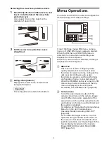
Removing the screw hole protective covers
1
Bend the tip of a thin rod about 2 mm, and
insert it into the hole of the screw hole
protective cover.
Use a paper clip or other object with a
diameter of about 1 mm.
2
Pull the screw hole protective covers
straight out.
Ratings label (bottom)
Displays the model name and electrical
ratings information.
The nameplate is located on the bottom.
Menu Operations
The menu control block is used to configure the
device settings and camera settings.
One of the three menus (RM menu, camera
menu, or FUNCTION menu) is always selected.
When the RM menu or FUNCTION menu is
selected, the menu items and settings are
displayed on the LCD panel.
When the camera menu is selected, nothing is
displayed on the LCD panel.
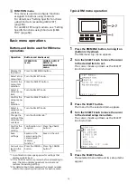
RM menu
This menu is used to configure picture
quality adjustments and compensation
functions on target cameras, configure the
unit, execute/configure auto assign
functions on cameras, and for performing
configuration from a connected setup PC.
When the RM MENU button is turned on, RM
menu setup mode is invoked and the top
menu is displayed on the LCD panel.
For details, see “RM Menu List” (page 68).
Camera menu
Turns the superimposed output of the
camera setup menu on the camera image
on/off. When turned on, operation of the
setup menu on the camera using the knobs
and buttons on the menu control block and
the joystick is enabled.
For details, see “Operating the Camera Setup
Menu from the Unit (Camera Menu
Operation Mode) (excluding ILME-FR7)”
For an ILME-FR7 target camera, it can be
operated using the knobs and buttons on
the menu control block. For details about
joystick operations, see “Operating with the
Screen Display Overlaid on the Camera
Image (CAM GUI Operation Mode) (ILME-
Important
ȩ
Ȫ
ȫ
Summary of Contents for RM-IP500
Page 86: ...Sony Corporation ...

