background image

Chapter 1 Introduction

7

Location and Function of Parts

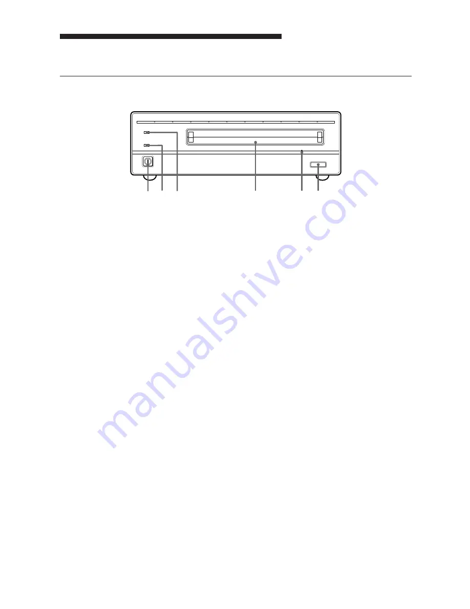
Front Panel

EJECT

POWER

BUSY

1 2 3

4

5 6

Fig. 1-2: Front View

1

POWER switch

Push the button to turn the power on and off.
The power is on when the button is in the
depressed position, and off when fully
protruding.

2

POWER indicator

The green lamp lights up when the power is
turned on.

3

BUSY indicator

As this disk is inserted and the drive becomes
ready for read/write operation, the BUSY
indicator turns green. The orange lamp lights
up when the disk unit is accessing or writing
data. This lamp flashes on and off at about 2-
second intervals when the unit overheats,
regardless of whether or not a disk is being
accessed.

4

Disk insertion slot

Insert the disk cartridge into this slot. Refer
to the section “Inserting a Disk Cartridge” on
page 13 for more information.

5

Emergency eject hole

If the disk cartridge cannot be ejected using
the EJECT button 

6

, turn off the power and

insert the supplied emergency eject tool into
this hole to trip the emergency eject
mechanism. Refer to the section “What to do
if the disk does not eject” on page 14 for
further details.

6

EJECT button

Press this button to eject the disk cartridge
from the disk unit. The EJECT button is
disabled with the function switch or software
settings prohibit ejection. When the write
cache is enabled, it may take a few moments
(up to 45 seconds) for the disk to eject
because data in the cache must first be
written to the disk.

Summary of Contents for RMO-S591

Page 1: ...User s Guide Mode d emploi Bedienungsanleitung Guía del usuario Istruzioni per l uso RMO S594 DW MO Disk Unit RMO S591 DW 3 860 688 11 1 ...

Page 2: ...Sony Corporation Printed in Japan 1997 RMO S594 DW MO Disk Unit RMO S591 DW ...

Page 3: ...adio frequency energy and if not installed and used in accordance with the instructions may cause harmful interference to radio communications However there is no guarantee that interference will not occur in a particular installation If this equipment does cause harmful interference to radio or television reception which can be determined by turning the equipment off and on the user is encouraged...

Page 4: ...ttaa altistaa käyttäjän turvallisuusluokan 1 ylittävälle näkymättömälle lasersäteilylle VARNING Om apparaten används på annat sätt än i denna bruksanvisning specificerats kan användaren utsättas för osynlig laserstrålning som överskrider gränsen för laserklass 1 ADVARSEL USYNLIG LASERSTRÅLING VED ÅBNING UNDGÅ UDSÆTTELSE FOR STRÅLING ADVARSEL USYNLIG LASERSTRÅLING NÅR DEKSEL ÅPNES UNNGÅ EKSPONERING...

Page 5: ...to this chapter when setting up the disk unit Chapter 3 Using the Disk Unit In this chapter you learn how to turn on the disk unit and how to insert and eject a disk cartridge Refer to this chapter when you are ready to actually begin using the disk unit Chapter 4 Precautions This chapter contains precautions regarding the use and operation of the disk unit and magneto optical disk cartridges It a...

Page 6: ...tical disk This is equivalent to about 1600 1800 times the capacity of a conventional 3 5 inch floppy disk 2HD Any disk conforming to the internationally accepted CCS continuous composite servo or CCW continuous composite write once format can be used in this disk unit This disk unit employs SCSI 2 Small Computer System Interface 2 The 3 600 min 1 3 600 rpm high speed spindle motor enables data tr...

Page 7: ...O IEC CD 14517 1024 bytes sector R W About 2 6 G bytes EDM 2600B ISO IEC CD 14517 512 bytes sector R W About 2 3 G bytes EDM 2300B ISO IEC 13549 1024 bytes sector R W About 1 3 G bytes EDM 1300B ISO IEC 13549 512 bytes sector R W About 1 2 G bytes EDM 1200B ISO IEC 10089 1024 bytes sector R About 650 M bytes EDM 650B ISO IEC 10089 512 bytes sector R About 600 M bytes EDM 600B ISO IEC CD 14517 1024...

Page 8: ...regardless of whether or not a disk is being accessed 4 Disk insertion slot Insert the disk cartridge into this slot Refer to the section Inserting a Disk Cartridge on page 13 for more information 5 Emergency eject hole If the disk cartridge cannot be ejected using the EJECT button 6 turn off the power and insert the supplied emergency eject tool into this hole to trip the emergency eject mechanis...

Page 9: ...ng the SCSI ID on page 11 for more information 3 SCSI connectors Plug SCSI cables sold separately linking the host computer and other SCSI peripherals into these connectors Note If the disk unit is the last device on the SCSI chain set function switch F to 1 to turn on the internal terminator When it is not the last device make sure that the terminator is off switch F is set to 0 4 Air duct The ai...

Page 10: ...y made set the SCSI ID using the SCSI ID switch and the disk unit s functions using the function switches RMO S594 DW S591 DW Magneto Optical Disk Unit AC power cord Emergency eject tool User s Guide Guide to Safe Use Safety Precautions Component and Accessory Check List Upon opening the carton check to see that you have all of the components and accessories listed below Contact your dealer immedi...

Page 11: ...switch F on the rear panel to 1 to turn on the internal terminator When it is not the last device make sure that the terminator is off function switch F is set to 0 The total length of the SCSI cables connected to a SCSI chain must not exceed six meters 19 feet 8 1 4 inches Connecting the Disk Unit A 1 B C D E F G H 0 SCSI CONNECTOR AC IN F GND SCSI ID Fig 2 2 Connecting the RMO S594 DW S591 DW to...

Page 12: ...ches A H on the rear panel to select the disk unit s functions in accordance with the host computer and software you are using Be sure to turn off the power before setting the switches A 1 B C D E F G H 0 Fig 2 4 Function Switches This disk unit is equipped with a write cache When the write cache is enabled never turn off the disk unit power without making sure that all data has been written to th...

Page 13: ...SI control Fast SCSI compatible Not Fast SCSI compatible E Force verify All write operations are verfied All write operations are normal operations with a verify pass without a verify pass F Terminator The internal terminator is on The internal terminator is off G Auto spin up Inserting a disk does not causes Inserting a disk causes the spindle motor to rotate the spindle motor to rotate H Manual ...

Page 14: ...ost computer Refer to the manual supplied with the host computer for the start up procedure Chapter 3 Using the Disk Unit Inserting a Disk Cartridge 3 Insert a disk cartridge with the side you want to use facing upwards Fig 3 2 Inserting a Disk Cartridge 4 Access or write data on the disk using software commands on the host computer The BUSY indicator lights up while the unit is accessing the disk...

Page 15: ...e out even when you press the EJECT button or use a software command under the following conditions The eject function has been disabled using the function switch or a software command The host computer is not functioning properly The disk unit has been turned off due to a power failure etc or Something is wrong with your disk unit itself When you cannot eject the disk cartridge using the EJECT bu...

Page 16: ...positionitatanangle Location requirements Carefulconsiderationshouldbegiventothe followinginselectingasitetoinstallorstore yourdiskunit Avoidthefollowingconditions Highhumidity Hightemperatures Directsunlight Dust Strongvibration Widetemperaturefluctuations Ventilation Careshouldbeexercisedtopreventtheinternal mechanismsofthediskunitfromoverheating Becarefulnottoclogorblockthevent orplace theuniti...

Page 17: ...Do not use any type of solvent such as alcoholorbenzine whichmaydamagethefinish On the Disk Cartridges Donotdropthediskcartridgeorsubjectitto anyviolentshocksorvibration Donotdisassemblethediskcartridge Itisa precisioncomponentandhasbeencarefully adjustedatthefactorypriortoshipment Donotopenthediskcartridge sshutter manuallyortouchthediskinside Theshutteris designedtoopenautomaticallywhenthe cartr...

Page 18: ...eneedto writeonthedisk Cleaning a Disk DustandstainsmayaccumulateonMOdisks whentheyareusedforalongperiodoftime To avoidresultantdataread writeerrors usean optionaldiskcleaner Tomaintainthehigh performanceandprolongtheusefullifeofyour MOdisk cleaningatleastonceeverythree monthsisrecommended Disk cleaning accessories UsethefollowingSonydiskcleaningkitordisk cleaner soldseparately MOA D51DiskCleaning...

Page 19: ...rate maximum 5Mbytes s synchronous Host interface SCSI 2 Small Computer System Interface 2 ANSI X3 131 1994 Operating environment Installation Horizontal 5 Temperature Operating 5 C to 40 C 41 F to 104 F gradient 10 C h or 18 F h Non operating 30 C to 60 C 22 F to 140 F Relative humidity Operating 10 to 85 no condensation Non operating 10 to 90 Laser Type Semiconductor AlGaInP laser Wavelength 685...

Page 20: ...s EDM 2300B 512 bytes sector 2 3 Gbytes EDM 1300B 1 024 bytes sector 1 3Gbytes EDM 1200B 512 bytes sector 1 2 Gbytes Continuous composite write once disks CWO 2600B 1 024 bytes sector 2 6 Gbytes CWO 2300B 512 bytes sector 2 3 Gbytes CWO 1300B 1 024 bytes sector 1 3 Gbytes CWO 1200B 512 bytes sector 1 2 Gbytes SCSI cables MOA C08 80 cm full pitch full pitch MOA D51 Disk Cleaning Kit ...

Page 21: ...eur 28 Chapitre 3 Fonctionnement du lecteur Insertion d une cartouche disque 30 Ejection d une cartouche disque 31 Chapitre 4 Précautions A propos du lecteur 32 Sécurité 32 Prévention des dommages 32 Autres points à prendre en compte 33 A propos des cartouches disques 33 Protection des données 34 Entretien 34 Nettoyage des disques 34 Appendice Spécifications 35 Lecteur 35 Accessoires en option 36 ...

Page 22: ...uction Ce chapitre contient un aperçu général du lecteur RMO S594 DW S591 DW portant sur ses caractéristiques la configuration du système ainsi que la localisation et la fonction des pièces Chapitre 2 Démarrage Ce chapitre explique comment raccorder ce lecteur à l ordinateur central et aux autres périphériques SCSI Il explique également le réglage de l adresse SCSI et des fonctions du lecteur Voir...

Page 23: ... disquette conventionnelle de 3 5 pouces 2HD Chapotre 1 Introduction Toute disquette conforme au format international CCS servo continu composite ou CCW écriture unique continu composite peut être utilisée dans cette unité de disquette Ce lecteur de disque utilise SCSI 2 Small Computer System Interface 2 Le moteur à broche grande vitesse 3 600 min 1 3 600 tr min permet la transmission des données ...

Page 24: ...B ISO IEC CD 14517 1024 octets secteur R W Environ 2 6 Go EDM 2600B ISO IEC CD 14517 512 octets secteur R W Environ 2 3 Go EDM 2300B ISO IEC 13549 1024 octets secteur R W Environ 1 3 Go EDM 1300B ISO IEC 13549 512 octets secteur R W Environ 1 2 Go EDM 1200B ISO IEC 10089 1024 octets secteur R Environ 650 Mo EDM 650B ISO IEC 10089 512 octets secteur R Environ 600 Mo EDM 600B ISO IEC CD 14517 1024 o...

Page 25: ...insertion de disque Insérer la cartouche disque dans ce logement Voir la section Insertion d une cartouche disque à la page 30 pour de plus amples informations 5 Trou d éjection de secours Si la cartouche disque ne peut être éjectée en utilisant la touche 6 EJECT mettre l appareil hors tension et insérer l outil d éjection de secours dans la fente pour déclencher le mécanisme d éjection de secours...

Page 26: ...cher les câbles SCSI vendus séparément reliant l ordinateur central et les autres périphériques dans ces connecteurs Remarque Si le lecteur est le dernier appareil de la chaîne SCSI régler le sélecteur de fonctions F sur 1 pour activer la terminaison interne Dans le cas contraire vérifier que la terminaison est désactivée le sélecteur F est réglé sur 0 4 Manche à air L air pour refroidir le lecteu...

Page 27: ...de fonction Liste de contrôle des composants et accessoires Ouvrir le carton et vérifier que tous les composants et accessoires indiqués ci dessous s y trouvent Contacter immédiatement son revendeur si l un d entre eux manque ou est abîmé Lecteur de disque magnéto optique RMO S594 DW S591 DW Cordon d alimentation secteur Outil d éjection de secours Mode d emploi Guide d utilisation de sécurité Pré...

Page 28: ... à 1 pour activer la terminaison interne Si ce n est pas le cas vérifier que la terminaison est désactivée sélecteur de fonction F réglé à 0 La longueur totale des câbles SCSI connectés à une chaîne SCSI ne doit pas dépasser 6 mètres 19 pieds 8 1 4 pouces A 1 B C D E F G H 0 SCSI CONNECTOR AC IN F GND SCSI ID Fig 2 2 Connexion du RMO S594 DW S591 DW Lecteur de disque magnéto optique RMO S594 DW S5...

Page 29: ...neau arrière selon l ordinateur central et le logiciel utilisés Bien mettre l appareil hors tension avant d effectuer ces réglages A 1 B C D E F G H 0 Fig 2 4 Sélecteurs de fonction L unité de disquette est équipée d une mémoire cache d écriture Lorsque la mémoire cache d écriture est activée ne jamais mettre l unité de disquette hors tension avant de s assurer que toutes les données ont été écrit...

Page 30: ...e parité SCSI invalide Mémoire cache désactivée Terminaison interne activée L insertion d un disque ne provoque pas la rotation du moteur à broche L insertion d un disque provoque la rotation du moteur à broche La cartouche de disque ne peut pas s éjecter en appuyant sur la touche EJECT La cartouche de disque peut s éjecter en appuyant sur la touche EJECT Fonction 1 0 Réglages usine Chapitre 2 Dém...

Page 31: ...émarrer l ordinateur central Voir le mode d emploi fourni avec l ordinateur central pour la procédure de démarrage 3 Insérer une cartouche disque la face à utiliser dirigée vers le haut Fig 3 2 Insertion d une cartouche disque 4 Accéder ou écrire des données sur le disque à l aide d instructions logicielles à l ordinateur central Le témoin BUSY s allume durant l accès au disque Que faire quand le ...

Page 32: ...uche EJECT ou si l on utilise des instructions logicielles La fonction d éjection a été invalidée par un sélecteur de fonction ou une instruction logicielle L ordinateur central ne fonctionne pas correctement Le lecteur a été coupé par une panne d électricité etc Le lecteur lui même a un problème Touch EJECT Procéder comme suit quand la cartouche disque ne peut pas être ejectée en appuyant sur la ...

Page 33: ...er de biais Chapitre 4 Précautions Exigences concernant l emplacement Tenir compte des points suivants lors de la sélection de l emplacement d installation ou de stockage du lecteur Eviter les conditions suivantes Forte humidité Hautes températures En plein soleil Poussière Forte vibration Fluctuations de température importantes Ventilation Prendre les précautions nécessaires pour éviter la surcha...

Page 34: ...er la finition Chapitre 4 Précautions A propos des cartouches disques Rangement des cartouches disques Ranger les cartouches disques dans leur boîte Ne pas les laisser en plein soleil ou sous une chaleur excessive sur le tableau de bord ou dans la boîte à gants d une voiture par exemple Ne pas ranger les cartouches disques dans les conditions suivantes Poussière excessive et débris En plein soleil...

Page 35: ...er le kit de nettoyage de disque ou le dispositif de nettoyage de disque Sony vendus séparément suivants Kit de nettoyage de disque MOA D51 Ne pas utiliser d autre dispositif de nettoyage de disque cela pourrait provoquer des erreurs d écriture lecture des données dues aux différences de caractéristiques de la surface des disques Voir le mode d emploi fourni avec chaque accessoire de nettoyage pou...

Page 36: ...hrone Interface d ordinateur central SCSI 2 Small Computer System Interface 2 ANSI X3 131 1994 Environnement de fonctionnement Installation Horizontale 5 Température Fonctionnement 5 à 40 C 41 à 104 F gradient de 10 C h ou 18 F h Non fonctionnement 30 à 60 C 22 à 140 F Humidité relative Fonctionnement 10 à 85 sans condensation Non fonctionnement 10 à 90 Laser Type Semi conducteur A1GaInP Longueur ...

Page 37: ...EDM 2300B 512 octets secteurs 2 3 Go EDM 1300B 1 024 octetssecteur 1 3 Go EDM 1200B 512 octets secteur 1 2 Go Disquettes d écriture unique continue composite CWO 2600B 1 024 octets secteur 2 6 Go CWO 2300B 512 octets secteur 2 3 Go CWO 1300B 1 024 octets secteur 1 3 Go CWO 1200B 512 octets secteur 1 2 Go Câbles SCSI MOA C08 80 cm pas entier pas entier MOA D51 Kit de nettoyage de disque Appendice ...

Page 38: ...ASER PRODUCT LASER KLASSE 1 PRODUKT 4 627 223 01 Achtung Zur Trennung vom Netz ist der Netzstecker aus der Steckdose zu ziehen welche sich in der Nähe des Gerätes befinden muß und leicht zugänglich sein soll Dieser Aufkleber befindet sich an der unt Unterseite des Gehäuses Diese Ausrüstung erfüllt die Europäischen EMC Bestimmungen für die Verwendung in folgender folgenden Umgebung en Wohngegenden ...

Page 39: ...ßen der Disk Einheit 45 Einstellen der SCSI ID 46 Einstellen der Funktionen der Disk Einheit 46 Kapitel 3 Bedienung Einlegen einer MO Disk 48 Auswerfen einer MO Disk 49 Kapitel 4 Zur besonderen Beachtung Für die Disk Einheit 50 Zur Betriebssicherheit 50 Zur Vermeidung von Schäden 50 Weitere wichtige Punkte 51 Für die MO Disks 51 Datenschutz 52 Reinigung 52 Reinigen von MO Disks 52 Anhang Technisch...

Page 40: ...pitel gibt einen Überblick über die Disk Einheit schneidet kurz die verschiedenen Merkmale und möglichen Systemkonfigurationen an und erklärt die Funktionselemente Kapitel 2 Betriebsvorbereitungen Dieses Kapitel beschreibt die Anschlüsse der Disk Einheit an den Host Rechner und andere SCSI Ausrüstungen Fernerhin werden die Einstellung der SCSI ID und die verschiedenen Funktionen der Disk Einheit e...

Page 41: ...Zoll Disketten 2HD Alle Disks die dem international anerkannten CCS Continuous Composite Servo oder CCW Format Continous Composite Write Once entsprechen können von dieser Disk Einheit benutzt werden Die Disk Einheit benutzt SCSI 2 Small Computer System Interface 2 Ein schneller Spindelmotor mit einer Drehzahl von 3600 min 1 ermöglicht Datentransfergeschwindigkeiten von 2 03 bis 4 6 MByte s 1024 B...

Page 42: ...GByte DOM 2300B ISO IEC CD 14517 1024 Bytes Sektor R W Etwa 2 6 GByte EDM 2600B ISO IEC CD 14517 512 Bytes Sektor R W Etwa 2 3 GByte EDM 2300B ISO IEC 13549 1024 Bytes Sektor R W Etwa 1 3 GByte EDM 1300B ISO IEC 13549 512 Bytes Sektor R W Etwa 1 2 GByte EDM 1200B ISO IEC 10089 1024 Bytes Sektor R Etwa 650 MByte EDM 650B ISO IEC 10089 512 Bytes Sektor R Etwa 600 MByte EDM 600B ISO IEC CD 14517 1024...

Page 43: ...heit und zwar ungeachtet ob eine Disk eingeschoben ist oder nicht 4 Einschubschlitz Schieben Sie hier eine MO Disk ein Weitere Einzelheiten entnehmen Sie bitte dem Abschnitt Einlegen einer MO Disk auf Seite 48 5 Not Auswerf Öffnung Läßt sich die Disk Kassette mit der EJECT Taste 6 nicht auswerfen schalten Sie das Gerät aus und schieben den mitgelieferten Not Auswerf Stift in diese Öffnung um den N...

Page 44: ...Seite 46 3 SCSI Schnittstellen Schließen Sie hier SCSI Kabel nicht im Lieferumfang der Disk Einheit an um die Verbindung mit dem Host Rechner und anderen SCSI Ausrüstungen herzustellen Zur Beachtung Ist die Disk Einheit die letzte Ausrüstung in der SCSI Kette stellen Sie den Funktionsschalter F auf 1 um den internen Abschluß Terminator einzuschalten Ist sie nicht die letzte Ausrüstung muß der Absc...

Page 45: ...en Sie danach die Funktionen und die SCSI ID der Disk Einheit über und die Funktionsschalter den SCSI ID Schalter ein Überprüfen des Verpackungsinhalts Überprüfen Sie nach dem Auspacken als erstes den Inhalt anhand der Liste weiter unten Wenn Komponenten fehlen oder beschädigt sind benachrichtigen Sie bitte sofort Ihren Fachhändler RMO S594 DW S591 DW MO Disk Disk Einheit Netzkabel Not Ausewrf Sti...

Page 46: ...ettung des Systems ist stellen Sie den Funktionsschalter F an der Rückwand auf 1 um die Disk Einheit intern abzuschließen Wenn sie nicht die letzte Ausrüstung im System ist muß der Funktionsschalter F auf 0 stehen Die Gesamtlänge aller SCSI Kabel in der SCSI Verkettung darf 6 Meter nicht überschreiten A 1 B C D E F G H 0 SCSI CONNECTOR AC IN F GND SCSI ID Abb 2 2 Anschließen der Disk Einheit SCSI ...

Page 47: ... der Funktionen der Disk Einheit Mit den Funktionsschaltern A bis H an der Rückwand lassen sich die Funktionen der Disk Einheit auf den Host Rechner und die jeweils verwendete Software einstellen Schalten Sie die Stromversorgung der Disk Einheit aus bevor Sie eine Einstellung Änderung der Funktionen vornehmen A 1 B C D E F G H 0 Abb 2 4 Funktionsschalter Diese Disk Einheit ist mit einem Schreib Ca...

Page 48: ...rung E Prüflesen erzwingen Alle Schreibvorgänge werden überprüft mit einem Prüfdurchlauf Alle Schreibvorgänge laufen normal ab kein Prüfdurchlauf F Abschlußwiderstand Interner Abschlußwiderstand eingeschaltet Automatischer Motorstart G Interner Abschlußwiderstand ausgeschaltet Spindelmotor läuft bei Einschieben einer Disk nicht an Spindelmotor läuft bei Einschieben einer Disk an H Manueller Auswur...

Page 49: ...2 3 GByte EDM 2600B 1024 Bytes Sektor 2 6 GByte EDM 2300B 512 Bytes Sektor 2 3 GByte EDM 1300B 1024 Bytes Sektor 1 3 GByte EDM 1200B 512 Bytes Sektor 1 2 GByte CWO 2600B 1024 Bytes sektor 2 6 GByte CWO 2300B 512 Bytes sektor 2 3 GByte CWO 1300B 1024 Bytes sektor 1 3 GByte CWO 1200B 512 Bytes sektor 1 2 GByte 1 Drücken Sie den POWER Schalter Daraufhin leuchtet der POWER Indikator zur Anzeige daß di...

Reviews: