25
Basic Operations
Basic Operations
3
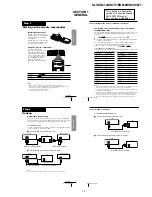
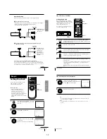
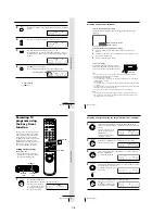
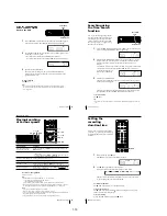
Press INPUT SELECT until a channel number appears in the display
window.
4
Press CH +/– to select the channel you want to record.
5
Press REC SPEED to select the tape speed, SP or EP.
EP (Extended Play) provides recording time three times as long as
SP (Standard Play). However, SP produces better picture and audio
quality.
6
Press
z
REC to start recording.
The recording indicator lights up red in the display window.
To stop recording
Press
x
STOP.
• CH
INPUT
SELECT
REC SPEED
REC
EP
VIDEO
APC
EP
VIDEO
APC
SP
VIDEO
APC
continued
Recording indicator
SP
VIDEO
APC
Basic Operations
26
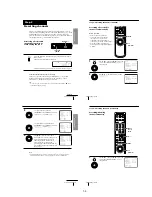
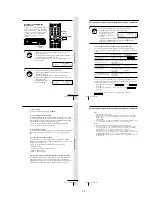
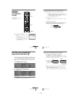
To check the remaining tape length
Press DISPLAY. The white bar indicates the approximate length of tape
remaining.
To watch another TV program while recording
1
Press TV/VIDEO to turn off the VIDEO indicator in the display
window.
2
If the TV is connected to the VCR’s LINE OUT jacks, set the TV to TV
input; if not, skip this step.
3
Select another channel on the TV.
To save a recording
To prevent accidental erasure, break off the
safety tab as illustrated. To record on the tape
again, cover the tab hole with adhesive tape.
Tips
• To select a channel, you can use the number buttons on the remote commander.
Enter the channel number, then press ENTER.
• (SLV-ED919KR and ED717KR)
You can select a video source from the LINE-1 IN or LINE-2 IN jacks using INPUT
SELECT or CH +/– buttons.
• (SLV-ED212KR)
You can select a video source from the LINE-1 IN jacks using INPUT SELECT or CH
+/– buttons.
• The display appears on the TV screen indicating information about the tape, but the
information won’t be recorded on the tape.
• If you don’t want to watch TV while recording, you can turn off the TV.
Notes
• The display doesn’t appear during still (pause) mode or slow-motion playback.
• It may take up to one minute for the VCR to calculate and display the remaining
tape length after you press DISPLAY.
Time counter
Remaining tape length
:
: 2
2
–
– –
0 0
0
Safety tab
Recording TV programs (continued)
27
Basic Operations
Basic Operations
Recording TV
programs using
the Easy Timer
function
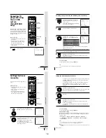
The Easy Timer function allows you to
make a timer recording of a program
without turning on your TV. Set the
recording timer to record only one
program that will be broadcast within
the next 24 hours using the EASY
TIMER knob. If the VCR clock has not
been set, you can also set the clock
before setting the timer recording.
Setting the Easy Timer
Before you start…
• Insert a tape with its safety tab in
place. Make sure the tape is longer
than the total recording time.
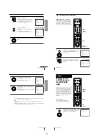
1
Push the EASY TIMER knob.
The START indicator appears in the display window.
If the clock has not been set,
“–:– –” appears. Go to step 2
in “Setting or changing the
Easy Clock” on page 29.
CH +/–
REC SPEED
ENTER (AM/PM)
1
2
3
4
5
6
7
8
9
0
EASY TIMER
SP
APC
START
AM
EASY
TIMER
EASY TIMER
knob
REC SPEED
SP/EP
C/–
continued
Basic Operations
28
Recording TV programs using the Easy Timer function (continued)
2
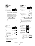
Set the recording start time by turning the EASY TIMER knob
clockwise or counterclockwise to increase or decrease the time by 15
minutes.
To increase or decrease the
time by one minute, press
C/–.
Press ENTER (AM/PM) to
change AM and PM.
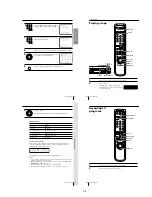
3
Push the EASY TIMER knob to confirm the start time setting.
The STOP indicator appears.
4
Set the recording stop time in the same way as in step 2, then push
the EASY TIMER knob.
A channel number flashes.
5
Turn the EASY TIMER knob clockwise or counterclockwise to select
the channel you want to record.
To select the tape speed, press
REC SPEED.
6
Push the EASY TIMER knob to confirm the setting.
The
t
indicator appears in
the display window and the
VCR stands by for recording.
EASY TIMER
EASY TIMER
REC SPEED
SP
APC
START
AM
EASY TIMER
EASY TIMER
SP
APC
STOP
PM
SP
APC
AM
EP
APC
SP
EASY TIMER
1-6
Summary of Contents for RMT-V310
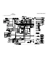
Page 24: ...SLV ED212 ED717 ED818 ED919 LF1 3 1 3 2 SECTION 3 BLOCK DIAGRAMS 3 1 OVERALL BLOCK DIAGRAM ...
Page 27: ...SLV ED212 ED717 ED818 ED919 LF1 3 4 AUDIO BLOCK DIAGRAM 3 7 3 8 ...
Page 28: ...SLV ED212 ED717 ED818 ED919 LF1 3 5 TUNER BLOCK DIAGRAM 3 9 3 10 ...
Page 29: ...SLV ED212 ED717 ED818 ED919 LF1 3 6 MODE CONTROL BLOCK DIAGRAM 3 11 3 12 ...


