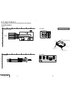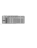
5-5E
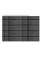
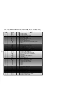
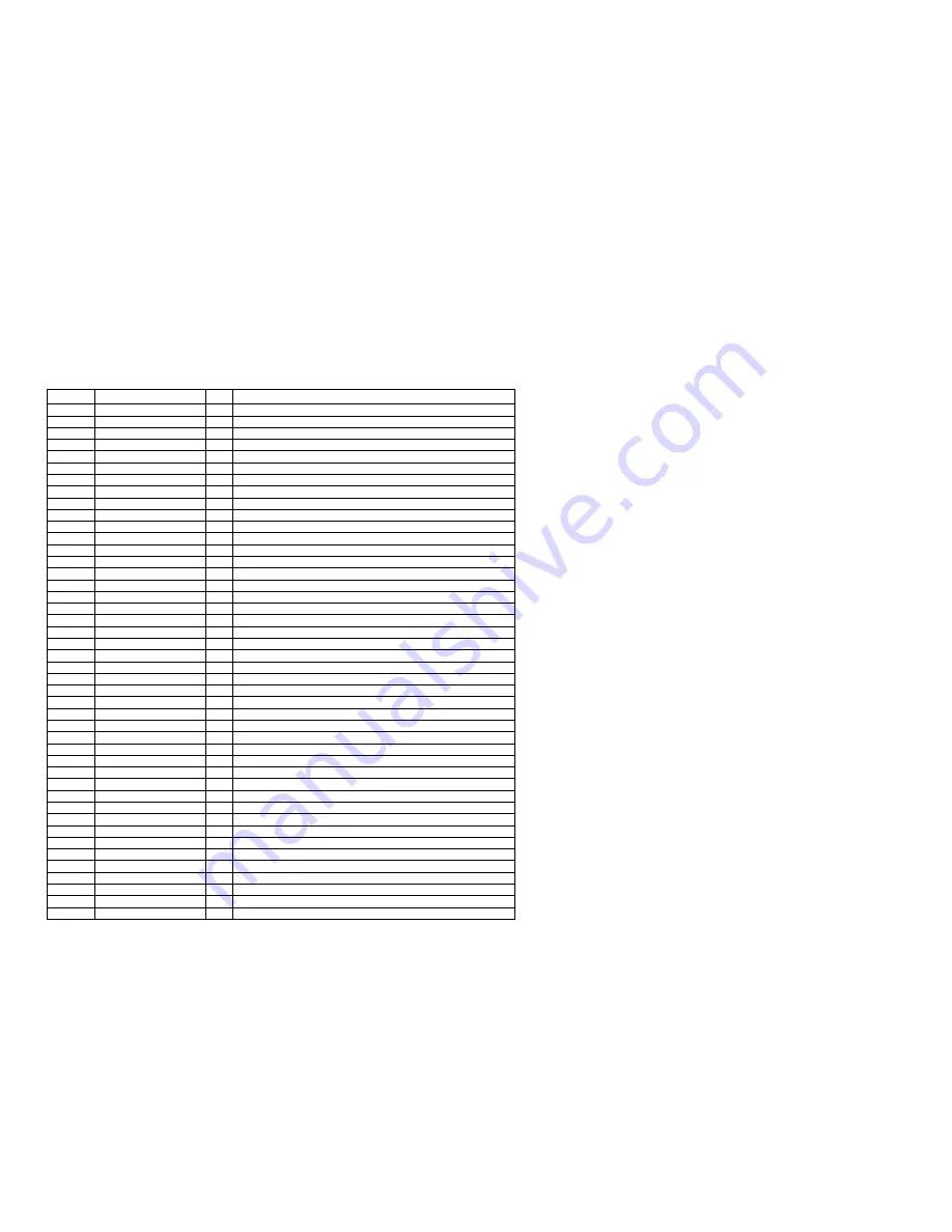
5-6. NICAM PROCESSOR PIN FUNCTION (NK-11 BOARD IC1)
Pin. No.
Pin Name
I/O
Function
1
OUT L
O
Analog signal output left
2
OUT R
O
Analog signal output right
3
VDD A1
–
Analog power supply 5V; DAC circuitry
4
VSS A1
–
Analog ground; DAC circuitry
5
VSS D1
–
Digital ground; DAC circuitry
6
VDD D1
–
Digital power supply 5V; DAC circuitry
7
VSS D2
–
Digital ground; DSP part
8
VDD D2
–
Digital power supply 5V; DSP part
9
TP2
I
Additional test pin 2; connected to ground for normal operation
10
N.C.
–
Not used
11
TP1
I
Additional test pin 1; connected to ground for normal operation
12
N.C.
–
Not used
13
N.C.
–
Not used
14
V TUNE
O
Tuning voltage output for crystal oscillator
15
XTAL I
I
Crystal oscillator input
16
XTAL O
O
Crystal oscillator output
17
TEST2
I
Test pin 2; connected to ground for normal operation
18
I REF
I
Resistor for reference current generation; front end circuitry
19
N.C.
–
Not used
20
VSS A2
–
Analog ground; analog front end circuitry
21
VDD A2
–
Analog power supply 5V; analog front end circuitry
22
TEST1
I
Test pin 1; connected to ground for normal operation
23
SIF2
I
Sound IF input 2
24
V REF1
I
Reference voltage; analog front end circuitry
25
SIF1
I
Sound IF input 1
26
C RST
Capacitor for power-on reset
27
VSS D3
–
Digital ground; front end circuitry
28
VDD D3
–
Digital power supply 5V; front end circuitry
29
SCL
I
Serial communication clock signal input
30
SDA
I
Serial communication data signal input
31
N.C.
–
Not used
32
N.C.
–
Not used
33
N.C.
–
Not used
34
N.C.
–
Not used
35
VDD D4
–
Digital power supply 5V; demodulator circuitry
36
VSS D4
–
Digital ground; demodulator circuitry
37
N.C.
–
Not used
38
N.C.
–
Not used
39
EXTI R
I
External audio input right channel
40
EXTI L
I
External audio input left channel
41
V REF2
I
Analog reference voltage digital-to-analog converter and operational amplifiers
42
N.C.
–
Not used
43
VDD A3
–
Analog power supply 5V; operational amplifiers
44
VSS A3
–
Analog ground; operational amplifiers
Summary of Contents for RMT-V310
Page 24: ...SLV ED212 ED717 ED818 ED919 LF1 3 1 3 2 SECTION 3 BLOCK DIAGRAMS 3 1 OVERALL BLOCK DIAGRAM ...
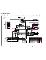
Page 27: ...SLV ED212 ED717 ED818 ED919 LF1 3 4 AUDIO BLOCK DIAGRAM 3 7 3 8 ...
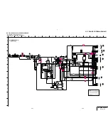
Page 28: ...SLV ED212 ED717 ED818 ED919 LF1 3 5 TUNER BLOCK DIAGRAM 3 9 3 10 ...
Page 29: ...SLV ED212 ED717 ED818 ED919 LF1 3 6 MODE CONTROL BLOCK DIAGRAM 3 11 3 12 ...

