1-11
44
Basic Operations
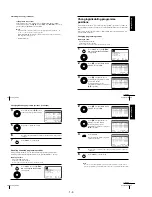
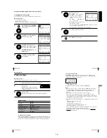
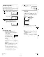
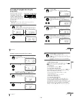
Daily/weekly recording
In step 4 above, press
m
to select the recording pattern. Each time you press
m
, the indication changes as shown below. Press
M
to change the indication
in reverse order.
today
t
DLY (Monday to Sunday)
t
W-SA (every Saturday) .....
t
W-SU (every Sunday)
t
1 month later
t
(dates count down)
t
today
To use the VCR after setting the timer
To use the VCR before a recording begins, just press
?/1
. The indicator
turns off and the VCR switches on. Remember to press
?/1
to reset the
VCR to recording standby after using the VCR.
You can also do the following tasks while the VCR is recording:
¥
Reset the counter (page 31).
¥
Display tape information on the TV screen (page 33).
¥
Check the timer settings (page 50).
¥
Watch another TV programme (page 34).
To use the Auto Tape Speed function
In step 4 above, press
m
to select AUTO. When you are recording a
programme in the SP mode and the remaining tape length becomes shorter
than the recording time, the recording tape speed is automatically changed
to the LP mode (or EP mode when you are recording NTSC signals). Note
that some noise will appear on the picture when the tape speed is changed.
To operate this function correctly, the TAPE SELECT setting in the
USER SET menu must be accurate (see page 58).
Tips
¥
To set the line input video source, you can also use the INPUT SELECT button.
¥
You can set the extended time for the G-CODE setting by 10, 20, 30, 40, 50, or 60
minutes. Set G-CODE EXTEND in the EASY OPERATION menu to the desired
extended time on page 59.
¥
To check, change, or cancel the programme setting, see Checking/changing/
cancelling timer settings on page 50.
¥
To record NTSC signals in EP mode, set the tape speed to LP. Even when timer
recording is set to LP mode, NTSC signals are automatically recorded in EP
mode.
Note
¥
The and
indicators flash in the display window when you press
?/1
with
no tape inserted.
Recording TV programmes using the G-CODE
¤
system (SLV-ED929MI
only) (continued)
45
Basic Operations
Basic Operations
Recording TV programmes using the
timer
You can preset a total of eight programmes, including settings made with other timer
methods.
Before you start
¥
Check that the VCR clock is set to the correct time and date.
¥
Insert a tape with its safety tab in place. Make sure the tape is longer than the total
recording time.
¥
Turn on your TV and set it to the video channel.
¥
Refer to Index to parts and controls for button locations.
1
Press MENU, then press
M
/
m
/
<
/
,
to highlight TIMER
PROGRAMMING and press OK.
2
Set the date, start and stop times
and tape speed:
1
Press
,
to select each item in
turn.
2
Press
M
/
m
to set each item.
To correct a setting, press
<
to
return to that setting and reset.
¥
To record the same programme every day or the same day every
week, see Daily/weekly recording on page 46.
¥
To record from other equipment connected to one or more of the
LINE inputs, press INPUT SELECT to display the connected line
in the PR position.
3
Press MENU to exit the menu.
OK
PLAY
continued
S E T
M E N U
:
:
O K
:
E N D
S E L E C T
— —
— — — —
— —
— —
—
— —
—
:
:
P R
D A Y
S T A R T
S T O P
— —
— — — —
— —
— —
—
— —
—
:
:
— —
— — — —
— —
— —
—
— —
—
:
:
— —
— — — —
— —
— —
—
— —
—
:
:
— —
— — — —
— —
— —
—
— —
—
:
:
— —
— — — —
— —
— —
—
— —
—
—
—
—
—
—
—
:
:
:
E X I T
S E T
M E N U
:
:
O K
:
E N D
S E L E C T
— —
— — — —
— —
— —
—
— —
—
:
:
P R
D A Y
S T A R T
S T O P
3 5
— — — —
— —
— —
—
— —
—
:
:
— —
— — — —
— —
— —
—
— —
—
:
:
— —
— — — —
— —
— —
—
— —
—
:
:
— —
— — — —
— —
— —
—
— —
—
:
:
— —
— — — —
— —
— —
—
— —
—
—
—
—
—
—
—
:
:
:
E X I T
OK
PLAY
INPUT
SELECT
MENU
MENU
46
Basic Operations
4
Press
?/1
to turn off the VCR.
The indicator appears in the display window and the VCR stands
by for recording.
To record from other equipment, leave the connected equipment
switched on.
To stop recording
To stop the VCR while recording, press
x
STOP.
Daily/weekly recording
In step 2 above, press
m
to select the recording pattern. Each time you press
m
, the indication changes as shown below. Press
M
to change the indication
in reverse order.
today
t
DLY (Monday to Sunday)
t
W-SA (every Saturday) .....
t
W-SU (every Sunday)
t
1 month later
t
(dates count down)
t
today
To use the VCR after setting the timer
To use the VCR before a recording begins, just press
?/1
. The indicator
turns off and the VCR switches on. Remember to press
?/1
to reset the
VCR to recording standby after using the VCR.
You can also do the following tasks while the VCR is recording:
¥
Reset the counter (page 31).
¥
Display tape information on the TV screen (page 33).
¥
Check the timer settings (page 50).
¥
Watch another TV programme (page 34).
To use the Auto Tape Speed function
In step 2 above, press
m
to select AUTO. When you are recording a
programme in the SP mode and the remaining tape length becomes shorter
than the recording time, the recording tape speed is automatically changed
to the LP mode (or EP mode when you are recording NTSC signals). Note
that some noise will appear on the picture when the tape speed is changed.
To operate this function correctly, the TAPE SELECT setting in the
USER SET menu must be accurate (see page 58).
Recording TV programmes using the timer (continued)
47
Basic Operations
Basic Operations
Tips
¥
To set the line input video source, you can also use the INPUT SELECT button.
¥
To check, change, or cancel the programme setting, see Checking/changing/
cancelling timer settings on page 50.
¥
To record NTSC signals in EP mode, set the tape speed to LP. Even when timer
recording is set to LP mode, NTSC signals are automatically recorded in EP
mode.
Note
¥
The and
indicators flash in the display window when you press
?/1
with
no tape inserted.
Summary of Contents for RMT-V408A
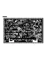
Page 28: ...3 1 MAIN PCB AUS 3 3 3 4 COMPONENT SIDE ...
Page 29: ...3 6 3 5 CONDUCTOR SIDE ...
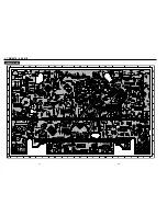
Page 30: ...3 2 MAIN PCB E HK ME 3 7 3 8 COMPONENT SIDE ...
Page 31: ...3 10 3 9 CONDUCTOR SIDE ...
Page 32: ...3 3 FUNCTION PCB Hi Fi MODEL 3 11 3 12E COMPONENT SIDE CONDUCTOR SIDE ...
Page 34: ... BLOCK IDENTIFICATION OF MAIN PCB Component Side Conductor Side 4 3 4 4 ...
Page 35: ...4 1 S M P S AUS PWR OFF PWR ON 1 2 4 6 4 5 ...
Page 36: ...4 2 S M P S E HK ME 4 7 4 8 PWR OFF PWR ON 1 2 ...
Page 37: ...4 3 POWER 4 10 4 9 ...
Page 38: ...6 5 7 3 4 0 8 9 4 4 SYSTEM CONTROL SERVO 4 11 4 12 ...
Page 41: ... VIDEOPROCESS IN VIDEOPROCESS OUT AUDIOPROCESS IN AUDIOPROCESS OUT qj 4 7 TM BLOCK 4 18 4 17 ...
Page 42: ... OSD VIDEO PROCESS IN OSD VIDEO PROCESS OUT qk 4 8 OSD VPS PDC 4 19 4 20 ...
Page 43: ...4 9 A2 NICAM ED925 ED929 EZ725 EZ727 4 21 4 22 ...
Page 45: ...4 11 SUB Hi Fi MODEL 4 25 4 26 ...
Page 48: ...4 32E MEMO ...


