1-15
60
Editing
Editing
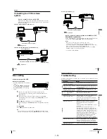
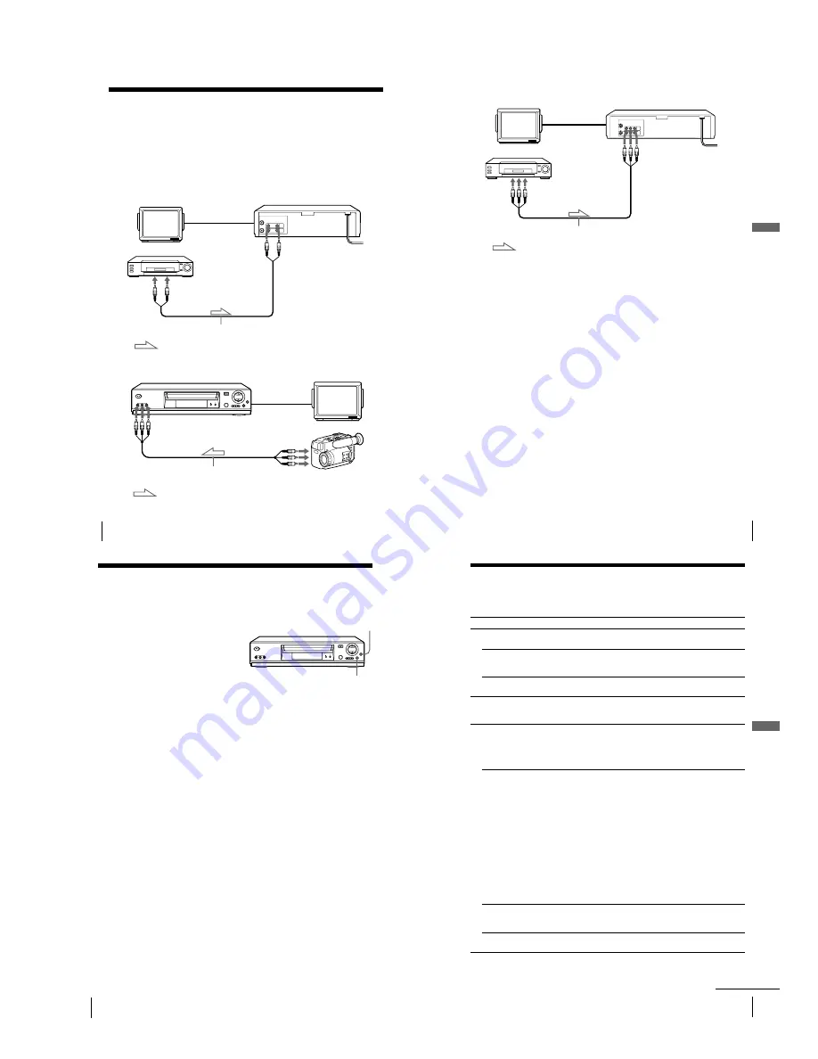
TV
Your VCR (Recorder)
LINE IN 1
Other VCR (Player)
LINE OUT
Audio/video cable (not supplied)
: Signal flow
Example B (SLV-ED929MI, ED925PS and ED828ME/SG only)
Your VCR (Recorder)
TV
LINE-2 IN
LINE OUT
VMC-820HG audio/video cable (not supplied)
Other VCR (Player)
: Signal flow
Connecting to a VCR or stereo
system
How to connect to record on this VCR
Connect the line outputs of the other VCR to the input connector of this
VCR. Refer to the examples A through C and choose the connection that
best suits your VCR.
Example A (SLV-ED323ME/SG and ED225PS only)
62
Editing
Basic editing
When recording on this VCR
Before you start editing
¥
Turn on your TV and set it to the video
channel.
¥
Press INPUT SELECT to display the
connected line in the display window.
¥
Press REC SPEED to select the tape
speed.
z
REC
1
Insert a source tape with its safety tab removed into the other
(playback) VCR. Search for the point to start playback and set it to
playback pause.
2
Insert a tape with its safety tab in place into this (recording) VCR.
Search for the point to start recording and press
X
PAUSE to set it to
playback pause.
3
Press
z
REC on this VCR to set it to recording pause.
4
To start editing, press the
X
PAUSE buttons on both VCRs at the same
time.
To stop editing
Press the
x
STOP buttons on both VCRs.
Tip
¥
To cut out unwanted scenes while editing, press
X
PAUSE on this VCR when an
unwanted scene begins. When it ends, press
X
PAUSE again to resume recording.
X
PAUSE
63
Additional Inf
ormation
Additional Information
Additional Information
Troubleshooting
If you have any questions or problems not covered below, please consult your nearest
Sony service facility.
Symptom
Remedy
Po
wer
The
?/1
ON/STANDBY
switch does not function.
¥
Connect the mains lead to the mains securely.
The power is turned on but the
VCR does not operate.
¥
Moisture condensation has occurred. Turn the power
off, unplug the mains lead and leave the VCR to dry
for over three hours.
The VCR is plugged in but the
display window remains dark.
¥
Set POWER SAVE in the USER SET menu to OFF
(see page 57).
Cloc
k
The clock has stopped and
—
—
:
—
—
appears in the
display window.
¥
The clock stops if the VCR is disconnected from the
mains. Reset the clock (and timer).
Playback
The playback picture does not
appear on the TV screen.
¥
Make sure the TV is set to the video channel. If you
are using a monitor, set it to video input.
¥
If you made connections using the aerial cable only,
make sure the RF channel number is set correctly for
your area.
The picture is not clear.
¥
Existing broadcasts may interfere with the VCR.
Reset the RF channel output of your VCR (see
page 17).
¥
Adjust the tracking with the TR/
—
buttons
on the VCR.
¥
The video heads are dirty (see the last page of
Troubleshooting). Clean the video heads using the
Sony T-25CLD, E-25CLDR, or T-25CLW video head
cleaning cassette. If these cleaning cassettes are not
available in your area, have the heads cleaned at your
nearest Sony service facility (a standard service
charge will be required). Do not use a commercially
available liquid type cleaning cassette other than
Sony s, as it may damage the video heads.
¥
The video heads may have to be replaced. Consult
your local Sony service facility for more information.
The picture has no colour.
¥
The COLOUR SYSTEM option in the USER SET
menu is set to the wrong position. Set the option to
conform to the system that the tape was recorded in.
The picture rolls vertically
during picture search.
¥
Adjust the vertical hold control on the TV or monitor.
continued
61
Editing
Editing
Example C (SLV-ED825PS only)
Your VCR (Recorder)
TV
LINE IN 1
Other VCR (Player)
LINE OUT
Audio/video cable (not supplied)
: Signal flow
How to connect to a stereo system (not available on SLV-
ED323ME/SG and ED225PS)
Connect the LINE-2 IN* jacks on this VCR to the audio output jacks on the
stereo system, using the RK-C510HG audio cable (not supplied).
Notes
¥
Make sure you connect the plugs to jacks of the same colour.
¥
If the other VCR is a monaural type, leave the red plugs unconnected.
¥
If you connect this VCR to both the LINE IN and LINE OUT jacks of the other
VCR, select the input correctly to prevent a humming noise.
¥
When you connect another VCR to the LINE-2 IN* connector, press INPUT
SELECT to display L2 in the display window.
* not available on SLV-ED825PS
Summary of Contents for RMT-V408A
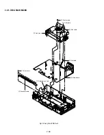
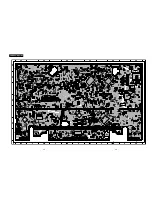
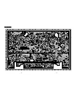
Page 28: ...3 1 MAIN PCB AUS 3 3 3 4 COMPONENT SIDE ...
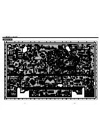
Page 29: ...3 6 3 5 CONDUCTOR SIDE ...
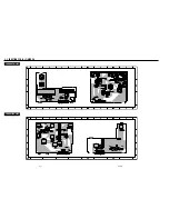
Page 30: ...3 2 MAIN PCB E HK ME 3 7 3 8 COMPONENT SIDE ...
Page 31: ...3 10 3 9 CONDUCTOR SIDE ...
Page 32: ...3 3 FUNCTION PCB Hi Fi MODEL 3 11 3 12E COMPONENT SIDE CONDUCTOR SIDE ...
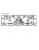
Page 34: ... BLOCK IDENTIFICATION OF MAIN PCB Component Side Conductor Side 4 3 4 4 ...
Page 35: ...4 1 S M P S AUS PWR OFF PWR ON 1 2 4 6 4 5 ...
Page 36: ...4 2 S M P S E HK ME 4 7 4 8 PWR OFF PWR ON 1 2 ...
Page 37: ...4 3 POWER 4 10 4 9 ...
Page 38: ...6 5 7 3 4 0 8 9 4 4 SYSTEM CONTROL SERVO 4 11 4 12 ...
Page 41: ... VIDEOPROCESS IN VIDEOPROCESS OUT AUDIOPROCESS IN AUDIOPROCESS OUT qj 4 7 TM BLOCK 4 18 4 17 ...
Page 42: ... OSD VIDEO PROCESS IN OSD VIDEO PROCESS OUT qk 4 8 OSD VPS PDC 4 19 4 20 ...
Page 43: ...4 9 A2 NICAM ED925 ED929 EZ725 EZ727 4 21 4 22 ...
Page 45: ...4 11 SUB Hi Fi MODEL 4 25 4 26 ...
Page 48: ...4 32E MEMO ...

