— 3 —
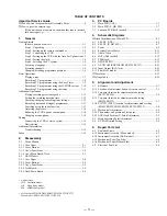
TABLE OF CONTENTS
Important Service Guide
◆
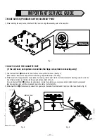
Mode Switch (Program Switch) Assembly Point ························· 4
◆
How to eject the cassette tape
(If the unit does not operate on condition that tape is inserted
into housing ass’y) ································································· 4
1.
General
Getting Started
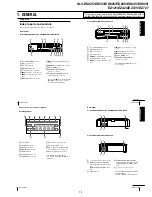
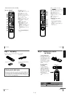
Index to parts and controls ················································· 1-1
Step 1 : Unpacking ····························································· 1-2
Step 2 : Setting up the remote commander ························· 1-2
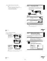
Step 3 : Connecting the VCR ············································· 1-3
Step 4 : Setting up the VCR with the Auto Set Up function 1-3
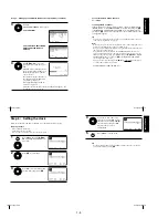
Step 5 : Setting the clock ···················································· 1-4
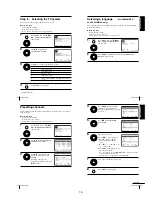
Step 6 : Selecting the TV system ········································ 1-5
Selecting a language ··························································· 1-5
Presetting channels ····························································· 1-5
Changing/disabling programme positions ·························· 1-6
Basic Operations
Playing a tape ····································································· 1-7
Recording TV programmes ················································ 1-8
Recording TV programmes using the Easy Timer ············· 1-9
Recording TV programmes using the G-CODE system ·· 1-10
Recording TV programmes using the timer ····················· 1-11
Additional Operations
Playing/searching at various speeds ································· 1-12
Setting the recording duration time ·································· 1-12
Checking/changing/cancelling timer settings ··················· 1-12
Recording stereo and bilingual programmes ···················· 1-13
Searching using the index function ·································· 1-13
Adjusting the picture ························································ 1-14
Reducing the VCR’s power consumption ························ 1-14
Changing menu options ···················································· 1-14
Editing
Connecting to a VCR or stereo system ····························· 1-15
Basic editing ····································································· 1-15
Additional Information
Troubleshooting ································································ 1-15
Index ··························································································· 1-16
2.
Disassembly
2-1
Mono Models
2-1-1 Case Upper ········································································· 2-1
2-1-2 Cover Bottom ····································································· 2-1
2-1-3 Ass’y-Panel Front ······························································· 2-2
2-1-4 Ass’y Main Board, Deck ···················································· 2-3
2-2
Hi-Fi Models
2-2-1 Case Upper ········································································· 2-4
2-2-2 Cover Bottom ····································································· 2-4
2-2-3 Ass’y-Panel Front ······························································· 2-5
2-2-4 Jack Board ·········································································· 2-5
2-2-5 Deck, Main Board ······························································ 2-6
3.
P.C.Boards
3-1
Main PCB (AUS) ································································ 3-3
3-2
Main PCB (E, HK, ME) ····················································· 3-7
3-3
Function PCB (Hi-Fi model) ············································ 3-11
4.
Schematic Diagrams
◆
Block Identification of Main PCB ············································ 4-3
4-1
S.M.P.S. (AUS) ··································································· 4-5
4-2
S.M.P.S. (E, HK, ME) ························································ 4-7
4-3
Power ·················································································· 4-9
4-4
System Control/Servo ······················································· 4-11
4-5
Audio/Video ····································································· 4-13
4-6
Hi-Fi (Hi-Fi model) ·························································· 4-15
4-7
TM-Block ········································································· 4-17
4-8
OSD/VPS/PDC ································································· 4-19
4-9
A2/NICAM (ED925/ED929/EZ725/EZ727) ··················· 4-21
4-10 Input-Output (RCA Jack) ················································· 4-23
4-11 Sub (Hi-Fi model) ···························································· 4-25
◆
Waveform ··············································································· 4-27
◆
Voltage Table ·········································································· 4-29
5.
Alignment and Adjustment
5-1
Reference ············································································ 5-1
5-1-1 Location of adjustment button of remote control ··············· 5-1
5-1-2 Test point location for adjustment mode setting
(EZ121/EZ424) ·································································· 5-2
5-1-3 Test point location for adjustment mode setting
(ED225/ED323) ·································································· 5-3
5-1-4 SW7T21 (TEST) location for adjustment mode setting
(ED825/ED828/ED925/ED929/EZ725/EZ727) ················· 5-4
5-2
Mechanical Adjustment ······················································ 5-5
5-2-1 The number and position of test point ································ 5-5
5-2-2 ACE Head Position (X-Point) Adjustment ························· 5-5
5-3
Head Switching Point Adjustment ····································· 5-6
5-4
NVRAM Option Setting ····················································· 5-6
6.
Repair Parts List
6-1
Exploded Views ·································································· 6-2
6-1-1 Instrument Assembly (Mono model) ·································· 6-2
6-1-2 Instrument Assembly (Hi-Fi model) ··································· 6-3
6-1-3 Mechanical Parts (Top Side) ·············································· 6-4
6-1-4 Mechanical Parts (Bottom Side) ········································· 6-5
6-2
Electrical Parts List ···························································· 6-6
• Abbreviation
AUS : Australia model
HK : Hong Kong model
ME : Middle East model
• Hi-Fi model: ED825/ED828/ED925/ED929/EZ725/EZ727
Mono model: ED225/ED323/EZ121/EZ424
Summary of Contents for RMT-V408A
Page 28: ...3 1 MAIN PCB AUS 3 3 3 4 COMPONENT SIDE ...
Page 29: ...3 6 3 5 CONDUCTOR SIDE ...
Page 30: ...3 2 MAIN PCB E HK ME 3 7 3 8 COMPONENT SIDE ...
Page 31: ...3 10 3 9 CONDUCTOR SIDE ...
Page 32: ...3 3 FUNCTION PCB Hi Fi MODEL 3 11 3 12E COMPONENT SIDE CONDUCTOR SIDE ...
Page 34: ... BLOCK IDENTIFICATION OF MAIN PCB Component Side Conductor Side 4 3 4 4 ...
Page 35: ...4 1 S M P S AUS PWR OFF PWR ON 1 2 4 6 4 5 ...
Page 36: ...4 2 S M P S E HK ME 4 7 4 8 PWR OFF PWR ON 1 2 ...
Page 37: ...4 3 POWER 4 10 4 9 ...
Page 38: ...6 5 7 3 4 0 8 9 4 4 SYSTEM CONTROL SERVO 4 11 4 12 ...
Page 41: ... VIDEOPROCESS IN VIDEOPROCESS OUT AUDIOPROCESS IN AUDIOPROCESS OUT qj 4 7 TM BLOCK 4 18 4 17 ...
Page 42: ... OSD VIDEO PROCESS IN OSD VIDEO PROCESS OUT qk 4 8 OSD VPS PDC 4 19 4 20 ...
Page 43: ...4 9 A2 NICAM ED925 ED929 EZ725 EZ727 4 21 4 22 ...
Page 45: ...4 11 SUB Hi Fi MODEL 4 25 4 26 ...
Page 48: ...4 32E MEMO ...


