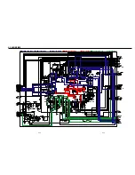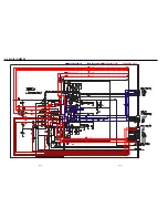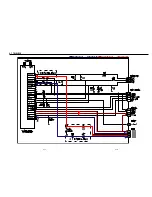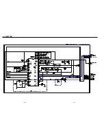
5-5
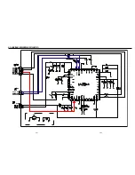
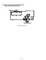
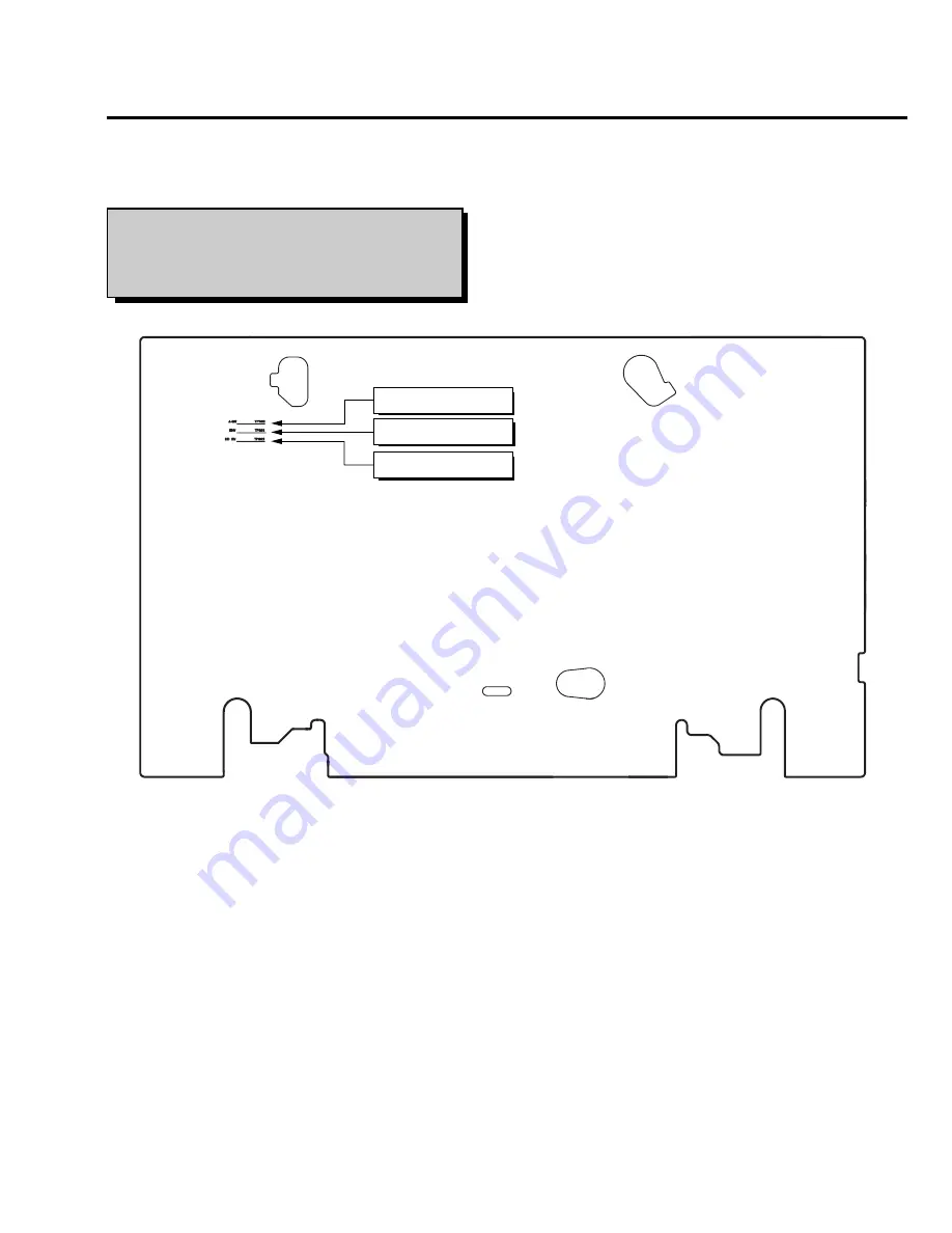
Fig. 5-5 Location of Test point (Main PCB-Top View)
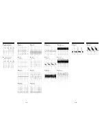
AUDIO OUTPUT
HEAD SWITCHING
ENVELOPE
Test point :
TP602 (H’D S/W -Trigger)
TP301 (Envelope)
TP302 (Audio output)
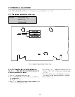
5-2 MECHANICAL ADJUSTMENT
Note : Refer to the Mechanical Manual for the adjustment and confirmation of ass’y deck.
5-2-1 The number and position of test point
5-2-2 ACE Head Position (X-Point) Adjustment
(See the 5-2-1(d) ACE Head Position (X-Point) Adjustment on
page 5-2 of the Mechanical Manual)
1) Playback the alignment tape (Color bar).
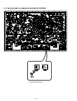
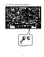
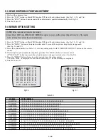
2) Press the “TEST” button on Main PCB/Function PCB to set
the adjustment mode.
(See Fig. 5-2, 5-3 and 5-4)
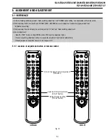
3) Press the “5” button of remote control then adjustment is op-
erated automatically. (See Fig. 5-1)
4) Connect the CH-1 probe to TP301 (Envelope) the CH-2
probe to TP602 (H’D switching pulse) and then trigger
to CH-1.
5) Insert the (-) driver into the X-Point adjustment hole
and adjust it so that envelope waveform is maximum.
6) Turn the Power off.
Summary of Contents for RMT-V408A
Page 28: ...3 1 MAIN PCB AUS 3 3 3 4 COMPONENT SIDE ...
Page 29: ...3 6 3 5 CONDUCTOR SIDE ...
Page 30: ...3 2 MAIN PCB E HK ME 3 7 3 8 COMPONENT SIDE ...
Page 31: ...3 10 3 9 CONDUCTOR SIDE ...
Page 32: ...3 3 FUNCTION PCB Hi Fi MODEL 3 11 3 12E COMPONENT SIDE CONDUCTOR SIDE ...
Page 34: ... BLOCK IDENTIFICATION OF MAIN PCB Component Side Conductor Side 4 3 4 4 ...
Page 35: ...4 1 S M P S AUS PWR OFF PWR ON 1 2 4 6 4 5 ...
Page 36: ...4 2 S M P S E HK ME 4 7 4 8 PWR OFF PWR ON 1 2 ...
Page 37: ...4 3 POWER 4 10 4 9 ...
Page 38: ...6 5 7 3 4 0 8 9 4 4 SYSTEM CONTROL SERVO 4 11 4 12 ...
Page 41: ... VIDEOPROCESS IN VIDEOPROCESS OUT AUDIOPROCESS IN AUDIOPROCESS OUT qj 4 7 TM BLOCK 4 18 4 17 ...
Page 42: ... OSD VIDEO PROCESS IN OSD VIDEO PROCESS OUT qk 4 8 OSD VPS PDC 4 19 4 20 ...
Page 43: ...4 9 A2 NICAM ED925 ED929 EZ725 EZ727 4 21 4 22 ...
Page 45: ...4 11 SUB Hi Fi MODEL 4 25 4 26 ...
Page 48: ...4 32E MEMO ...

