
S95E Sony
32
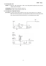
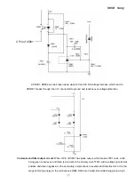
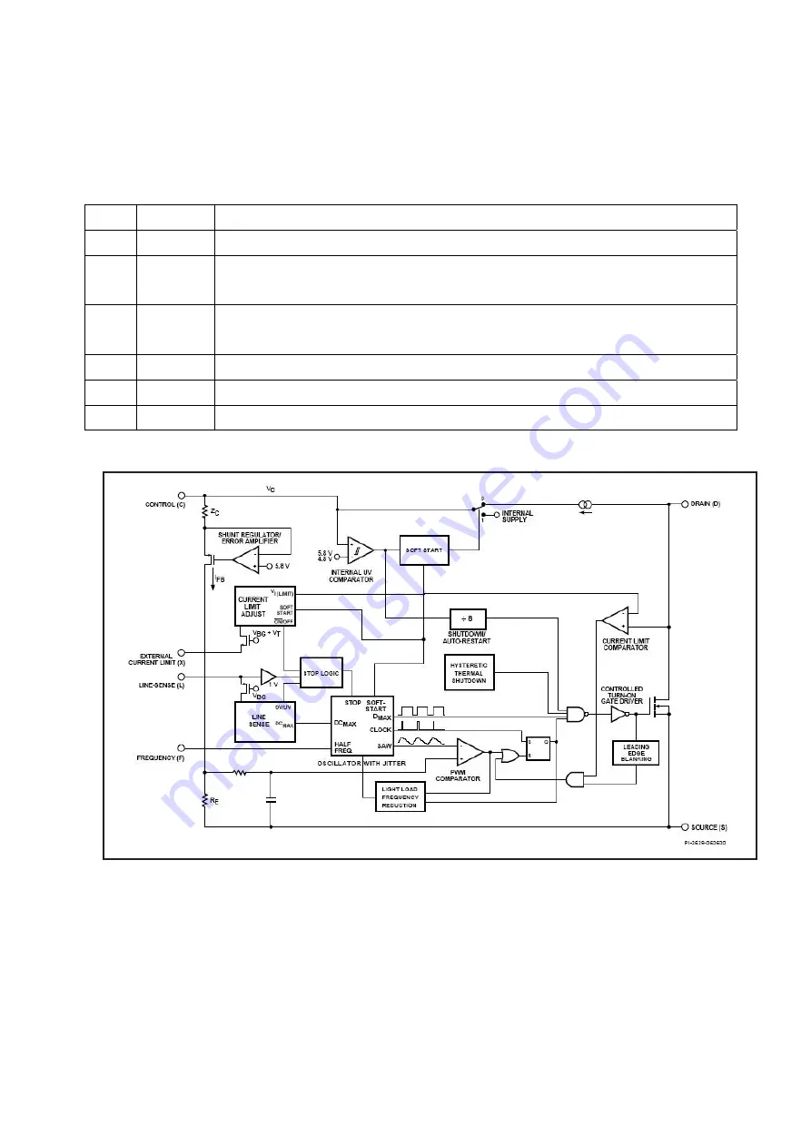
5.2.2 Introduction of IC
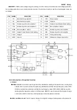
TOP247Y:
It cost effectively integrating the high voltage power MOSFET, PWM control, fault protection and
other control circuitry onto a single CMOS chip. The function of each pin and the inside circuit diagram are as
follows
:
Pin Symbol
Functional
Description
1
C
Control Pin, Error amplifier and feedback current input pin for duty cycle control
2 L
Line-Sense Pin, Input pin for OV, UV, line feed forward with DCMAX reduction,
remote ON/OFF and synchronization
3 X
External Current Limit Pin, Input pin for external current limit adjustment, remote
ON/OFF and synchronization
4
S
Source Pin, Output MOSFET source connection for high voltage power return
5
F
Frequency Pin, Input pin for selecting switching frequency
7
D
Drain Pin, High voltage power MOSFET drain output
Summary of Contents for S95E
Page 1: ...S95E Sony 1 Service Manual TFT LCD COLOR COMPUTER DISPLAY SONY ...
Page 3: ...S95E Sony 3 1 Precaution Warning on power connections Installation ...
Page 4: ...S95E Sony 4 Handing the LCD screen Maintenance Transportation ...
Page 10: ...S95E Sony 10 Adjustment steps of each menu ...
Page 11: ...S95E Sony 11 ...
Page 12: ...S95E Sony 12 ...
Page 13: ...S95E Sony 13 ...
Page 14: ...S95E Sony 14 ...
Page 15: ...S95E Sony 15 ...
Page 16: ...S95E Sony 16 ...
Page 17: ...S95E Sony 17 ...
Page 18: ...S95E Sony 18 ...
Page 19: ...S95E Sony 19 ...
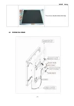
Page 26: ...S95E Sony 26 The panel is disassembled absolutely 4 2 WIRING DIAGRAM ...
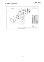
Page 27: ...S95E Sony 27 4 3 Monitor Exploded View ...
Page 39: ...S95E Sony 39 ...
Page 63: ...S95E Sony 63 8 Schematic ...
Page 64: ...S95E Sony 64 ...
Page 65: ...S95E Sony 65 ...
Page 66: ...S95E Sony 66 ...
Page 67: ...S95E Sony 67 ...
Page 68: ...S95E Sony 68 ...
Page 69: ...S95E Sony 69 ...


