

S95E Sony
36
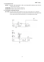
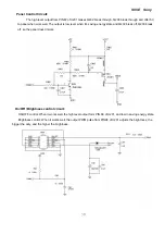
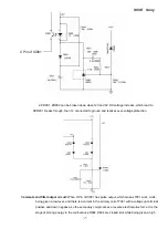
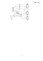
level, The primary coil produces a EMF with its down terminal positive and up negative, and
the
secondary coil appears a reverse EMF at the same time, then D902, D904 get through
accompanied with a voltage output of 12V and 5V through C904, C909 which are used to filter.
R901, C918 contained in the RC circuit is used to absorb the surge voltage produced by D902,
while R909, C907 is use to absorb the surge voltage produced by D904.
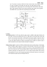
b. Inverter
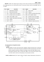
Input interface section:
1.12V DC input, offered by power section; 2. ON/OFF enable signal, offered by
Pin
68 of U201 in the main board with its value of 0V or 5V. When OFF=0V, the inverter doesn’t work, while
OFF=5V, it works under normal situation. 3. DIM signal for luminance modulation, offered by
Pin 98 of
U201 in the main board with its range of 0~5V. The Inverter offers different currents to the loads
because of the different feedback of voltage to the feedback-terminal of PWM. The smaller the value of
DIM, the smaller the current output of Inverter, the darker the brightness.
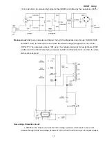
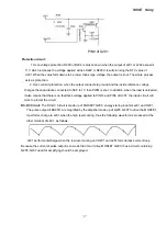
Voltage start-up circuit:
It consists of a PNP and a NPN transistor with two working stages. The first stage:
When the ON/OFF enables voltage is 0V, the Q201 is closed and Q202 is closed too. The DC voltage
at collector of Q202 can’t be applied to PIN9 of U201, so there are no pulse output at PIN10 and PIN7.
Hence, the Inverter don’t work. The second stage: ON/OFF is high level, Q201 gets through and base
of Q202 is pulled down, thus Q202 gets through. Then 12V voltage is applied to PIN9 of U201 resulting
in the operation of IC. Hence, U201 produces pulse output to control switch transistor, and the Inverter
which applied high voltage across the backlight works well.
Summary of Contents for S95E
Page 1: ...S95E Sony 1 Service Manual TFT LCD COLOR COMPUTER DISPLAY SONY ...
Page 3: ...S95E Sony 3 1 Precaution Warning on power connections Installation ...
Page 4: ...S95E Sony 4 Handing the LCD screen Maintenance Transportation ...
Page 10: ...S95E Sony 10 Adjustment steps of each menu ...
Page 11: ...S95E Sony 11 ...
Page 12: ...S95E Sony 12 ...
Page 13: ...S95E Sony 13 ...
Page 14: ...S95E Sony 14 ...
Page 15: ...S95E Sony 15 ...
Page 16: ...S95E Sony 16 ...
Page 17: ...S95E Sony 17 ...
Page 18: ...S95E Sony 18 ...
Page 19: ...S95E Sony 19 ...
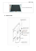
Page 26: ...S95E Sony 26 The panel is disassembled absolutely 4 2 WIRING DIAGRAM ...
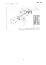
Page 27: ...S95E Sony 27 4 3 Monitor Exploded View ...
Page 39: ...S95E Sony 39 ...
Page 63: ...S95E Sony 63 8 Schematic ...
Page 64: ...S95E Sony 64 ...
Page 65: ...S95E Sony 65 ...
Page 66: ...S95E Sony 66 ...
Page 67: ...S95E Sony 67 ...
Page 68: ...S95E Sony 68 ...
Page 69: ...S95E Sony 69 ...


