72
SCD-C555ES
RF Level Check
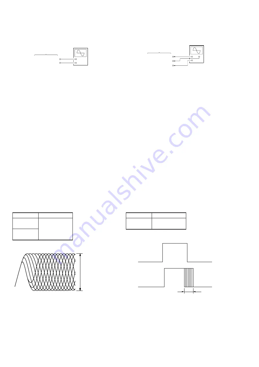
Connection:
Checking Method:
1. Under the condition of traverse waveform check mode in step
4, press the
[ AMS ]
dial.
2. Connect an oscilloscope to the TP703 (RFAC) and TP704
(AGND) on the MAIN board.
3. After “WAIT” is displayed, the RF waveform check mode will
become active and “PLAY 5th” will be displayed, and the 5th
music on the disc will be played.
4. Check that the RF waveform is clear and the level satisfies the
specification.
5. Press the
[ AMS ]
dial, and “GAISHU” will be displayed
and the outward track of the disc will be played.
6. Check that the RF waveform is clear and the level satisfies the
specification.
7. Press the
[ AMS ]
dial, and “NAISHU” will be displayed
and the inward track of the disc will be played.
8. Check that the RF waveform is clear and the level satisfies the
specification.
9. After checking, press the
[ AMS ]
dial, and the test is
over when “BU MEASURE” is displayed.
10. Press the
[OPEN/CLOSE]
button to open the tray, and remove
the test disc.
11. Using each type of disc, repeat from step 1 of S curve wave-
form check up to step 10 of RF level check.
12. When the check is over, press the
[POWER]
button to turn the
power off.
Note:
Take care not to leave the test disc in the set.
Specified Value:
Disc
A
SATD-S5 or
SATD-S4
PATD-012 or
0.9 to 1.5 Vp-p
YEDS-18
Note:
Clear RF waveform refers to the waveform where
◊
shapes should
be distinctively observed in the center.
Checking and Connecting Location : See page 68.
MAIN board
TP703 (RFAC)
TP704 (AGND)
+
–
oscilloscope
VOLT/DIV: 200 mV
TIME/DIV: 500 ns
RF signal waveform
A
CLV Jitter Check (CD only)
Connection:
Checking Method:
1. Set the test mode.
2. Connect an oscilloscope to the TP516 (RFCK) (CH1), TP517
(WFCK) (CH2) and TP808 (DG) (GND) on the MAIN board.
3. Place the test disc PATD-012 or YEDS-18 on the tray, and
close the tray.
4. Rotate the
[ AMS ]
dial to select “61 DISC DETECT”,
and press the
[ AMS ]
dial to enter. Then, the disc type
will be judged.
5. Check that the disc type has been judged.
(For the PATD-012, “DSKMOD CD” will be displayed. Refer
to the test mode, DISC DETECT command (page 55))
6. Rotate the
[ AMS ]
dial to select “86 ALL SRV ON”,
and press the
[ AMS ]
dial. Then, the disc will rotate,
automatic adjustment will be carried out, and all servos will
be turned on.
7. Rotate the
[ AMS ]
dial to select “07 DSP MON3”, and
press the
[ AMS ]
dial to enter.
8. Check that the value
A
of waveform on the oscilloscope sat-
isfies the specification.
9. Rotate the
[ AMS ]
dial to select “19 ALL SRV OFF”,
and press the
[ AMS ]
dial. Then, all servos will be
turned off and the disc rotation will stop.
10. Press the
[OPEN/CLOSE]
button to open the tray, and remove
the test disc.
11. Press the
[POWER]
button to turn the power off.
Note:
Take care not to leave the test disc in the set.
Specified Value:
Disc
A
PATD-012 or
50
µ
sec or less
YEDS-18
Checking and Connecting Location : See page 68.
MAIN board
TP516 (RFCK)
TP517(WFCK)
TP808 (DG)
+
+
–
oscilloscope
(CH2)
(CH1)
A
CLV jitter waveform
l
L
l
L
l
L
l
L
l
L
l
L
l
L
l
L
l
L
l
L
l
L
l
L
Summary of Contents for SCD-C555ES - Super Audio Cd
Page 18: ...18 18 SCD C555ES 4 2 SCHEMATIC DIAGRAM RF SECTION Refer to page 40 for Waveforms IC B D 390p ...
Page 28: ...28 28 SCD C555ES 4 12 SCHEMATIC DIAGRAM AUDIO SECTION 2 2 Page 31 Page 31 IC B D ...
Page 29: ...29 29 SCD C555ES 4 13 SCHEMATIC DIAGRAM D POWER SECTION ...
Page 34: ...34 34 SCD C555ES 4 19 SCHEMATIC DIAGRAM HP SECTION TO AUDIO BOARD 1 2 Page 27 ...
Page 38: ...38 38 SCD C555ES 4 23 SCHEMATIC DIAGRAM POWER SECTION 27 ...


