25
SCD-XE600
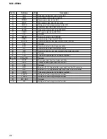
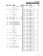
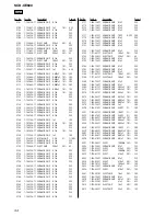
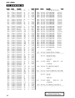
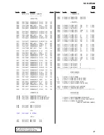
• IC Pin Function Description
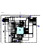
MAIN BOARD IC705 HD6432238RN57TEV (MASTER CONTROL)
Pin No.
Pin Name
I/O
Description
1
SDATA_DAC
O
Serial data output to the D/A converter
2
SCLK_DAC
O
Serial data transfer clock signal output to the D/A converter
3
SLATR_DAC
O
Serial data latch pulse output to the D/A converter
4 to 11
CD0 to CD7
I/O
Two-way data bus with the DSP
12
CVCC
–
Power supply terminal (+3.3V)
13
CA0
O
Address signal output to the DSP
14
VSS0
–
Ground terminal
15 to 22
CA1 to CA8
O
Address signal output to the DSP
23, 24
PB1, PB2
O
Not used
25
LOAD_S0
I
Loading in switch input terminal
26
LOAD_S2
I
Detection signal input for disc tray open Not used
27
LOAD_S1
I
Loading out switch input terminal
28
TSENS
I
Not used
29
DSENS
I
Disc in detection signal input terminal Not used
30
TRAY_IN
O
Control signal for loading motor drive
31
RS232CTx
O
Not used
32
RS232CRx
I
Not used
33
TRAY_OUT
O
Control signal for loading motor drive
34
P10
O
Not used
35
DRV_ON
O
Stop signal output for the sled motor and focus/tracking coil
36
SP_ON
O
Stop signal output for the spindle motor
37
P13
O
Not used
38
XLDON
O
Laser diode on/off control signal output to the RF amplifier
39, 40
TRMP, TRMM
O
Tray motor control signal output terminal Not used
41
P17
O
Not used
42
AVSS
–
Ground terminal
43
DIAG
I
Not used
44
P96
I
Not used
45 to 50
P47 to 42
I
Not used
51
MODEL
I
Setting terminal for model discrimination
52
JIT
I
Jitter value input from the DSP
53
VREF
I
Reference voltage input terminal
54
AVCC
–
Power supply terminal (+3.3V)
55, 56
MD0, MD1
I
Setting terminal for the CPU operational mode
57
OSC2
O
Sub system clock output terminal Not used
58
OSC1
I
Sub system clock input terminal Not used
System reset signal input from the reset signal generator “L”: reset
59
XRES
I
For several hundreds msec. after the power supply rises, “L” is input, then it
changes to “H”
60
XNMI
I
Non-maskable interrupt signal input terminal Not used
61
XSTBY
I
Standby on/off control signal input terminal Not used
62
VCC
–
Power supply terminal (+3.3V)
63
XTAL
–
System clock terminal (12.5 MHz) Not used
64
VSS1
–
Ground terminal
65
EXTAL
I
System clock input terminal (11.2896 MHz)
66
FWE
I
Write enable signal input for flash memory Not used
67
MD2
I
Setting terminal for the CPU operational mode
68
PF7
I
Not used


