SDM-P82(UC)
2-5
(4) Select COLOR TEMP
→
6500K in the service mode menu, and set the data
listed below as initial data for adjustment.
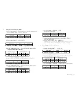
(5) Adjust the SUB-BRIGHTNESS: R, G, and B. Specifications are listed below.
7.
Setting for shipping
Turn off the power with the POWER button in the front panel. Check that the red
POWER LED lights on, and then execute the all mode recall. (press the POWER
button with pressing the OK button in the power-off state)
SUB-BRIGHTNESS
R
40
G
40
B
40
SUB-CONTRAST
R
130
G
130
B
130
x
y
0.313
±
0.003
Brightness (cd/m
2
)
0.329
±
0.003
14
±
0.7
2-5. Action after Replacing the LCD Panel and Board
1.
After replacing the LCD panel
(1) White balance adjustment. (Refer to Section 2-4.)
(2) CLEAR ETI TIME. (Refer to Section 2-3 step 3.)
(3) Check of picture and sound.
2.
After replacing the A board
(1) White balance adjustment. (Refer to Section 2-4.)
(2) EDID writing.
As the write protection is not applied in this unit, it is possible to write data
with an ordinary writing fixture.
It is required to be written for INPUT1: DVI-D, INPUT1: HD15, and
INPUT2: HD15 respectively.
Take care that the data for DVI-D and HD15 terminals are different
from each other.
(3) EDID copy to the EEPROM and ETI clear. (Refer to Section 2-1 step 6.)
Be sure to perform them after EDID writing. After executing, check
that the correct model information is displayed. (Refer to Section 2-1 step 1.)
(4) Operation check of buttons and LED's in the front panel, and Check of
picture and sound for respective inputs.
3.
After replacing the I board
(1) White balance adjustment. (Refer to Section 2-4.)
(2) Check of picture and sound.
4.
After replacing the G board
(1) Operation check of the MAIN POWER switch.
(2) Check of picture and sound.
5.
After replacing the H board
(1) Operation check of buttons and LED's in the front panel.
Summary of Contents for SDM-P82
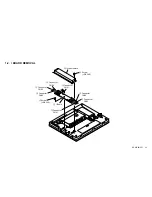
Page 11: ...SDM P82 UC 1 6 1 6 LCD PANEL REMOVAL 2 LCD panel 1 Two screws PWH 3X6 1 Two screws PWH 3X6 ...
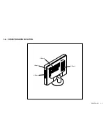
Page 19: ...SDM P82 UC 3 2 3 2 CIRCUIT BOARDS LOCATION G Board A Board I Board H Board ...
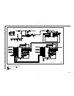
Page 31: ...SDM P82 UC 3 13 H BOARD H KEY COMPONENT SIDE CONDUCTOR SIDE ...
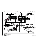
Page 33: ...SDM P82 UC 3 15 I BOARD I INVERTER COMPONENT SIDE CONDUCTOR SIDE ...
Page 35: ...SDM P82 UC 3 17 G BOARD G POWER SUPPLY COMPONENT SIDE CONDUCTOR SIDE ...

