SDM-P82(UC) 3-5
1
A
B
C
D
E
F
G
H
I
J
2
12
13
11
10
9
8
7
6
5
4
3
14
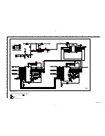
SW
EEPROM
A
-
b
(DVI AND DDC SWITCH IC)
ag 3
bd 5
bc6
bg7
bc8
+5V
bg 9
bg 10
INPUT 1
DVI-D INPUT
(DIGITAL RGB)
B-SS3627<J..>-A..-P2
4.4
4.4
4.4
4.4
4.4
4.9
4.9
4.4
0
4.8
4.9
•
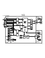
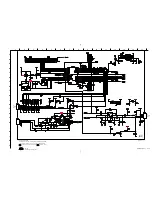
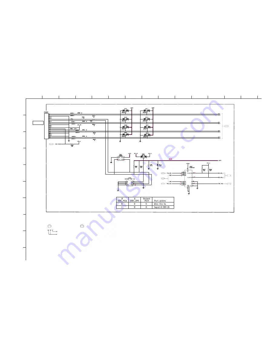
Divided circuit diagram
One sheet of A board are circuit diagram is divided into eight sheets,
each having the code A-
a
to A-
g
. For example, the destination
ab1 on the code A-
a
sheet is connected to ab1 on the A-
b
sheet.
a b 1
Ref. No.
Circuit diagram division code
Summary of Contents for SDM-P82
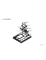
Page 11: ...SDM P82 UC 1 6 1 6 LCD PANEL REMOVAL 2 LCD panel 1 Two screws PWH 3X6 1 Two screws PWH 3X6 ...
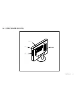
Page 19: ...SDM P82 UC 3 2 3 2 CIRCUIT BOARDS LOCATION G Board A Board I Board H Board ...
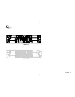
Page 31: ...SDM P82 UC 3 13 H BOARD H KEY COMPONENT SIDE CONDUCTOR SIDE ...
Page 33: ...SDM P82 UC 3 15 I BOARD I INVERTER COMPONENT SIDE CONDUCTOR SIDE ...
Page 35: ...SDM P82 UC 3 17 G BOARD G POWER SUPPLY COMPONENT SIDE CONDUCTOR SIDE ...

