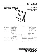
background image

SERVICE MANUAL

SPECIFICATIONS

SDM-S51

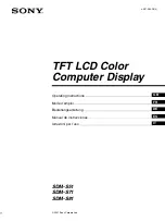
TFT LCD Color Computer DISPLAY

US Model

Canadian Model

AEP Model

LCD panel

Panel type: a-Si TFT Active Matrix
Picture size: 15.0 inch
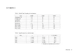
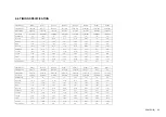
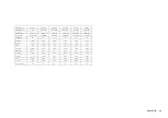
Input signal format

RGB operating frequency*
Horizontal: 28 -  60 kHz
Vertical: 48 -  75 Hz

Resolution

Horizontal: Max.1024 dots
Vertical: Max.768  lines

Input signal levels

RGB video signal

0.7 Vp-p, 75

, positive

SYNC signal

TTL level, 2.2 k , 
positive or negative
(Separate horizontal and vertical, 
or composite sync)
0.3 Vp-p, 75

, negative 

(Sync on green) 

Power requirements

100 -  240 V, 50 -  60 Hz, 
Max. 0.56A

DC input

DC 12 V (supplied AC adapter)

Power consumption

Max. 25 W

Operating temperature

5 -  35 

°

C

Dimensions (width/height/depth)

Display (upright): 

Approx. 387   330  175 mm
(15 

1

/

4


13 


7

  inches) 

(with stand)
Approx. 387  281  48 mm
(15 

1

/

4

×

 11 

1

/

 1 

15

/

16

 inches) 

(without stand)

Mass

Approx. 3.7 kg ( 8 lb 3  oz)  (with 
stand)
Approx. 2.9 kg (6 lb 5 oz)
(without stand)

Plug & Play

DDC2B

Accessories

See page 7.

* Recommended horizontal and vertical timing condition

  Horizontal sync width duty should be more than 4.8% of total 

horizontal time or 0.8 

µ

s, whichever is larger.

  Horizontal blanking width should be more than 2.5 

µ

sec.

  Vertical blanking width should be more than 450 

µ

sec.

Design and specifications are subject to change without notice.

×

×

×

×

×

×

×

Summary of Contents for SDM-S51

Page 1: ...0 240 V 50 60 Hz Max 0 56A DC input DC 12 V supplied AC adapter Power consumption Max 25 W Operating temperature 5 35 C Ω Dimensions width height depth Display upright Approx 387 330 175 mm 15 1 4 13 7 inches with stand Approx 387 281 48 mm 15 1 4 11 1 8 1 15 16inches without stand Mass Approx 3 7 kg 8 lb 3 oz with stand Approx 2 9 kg 6 lb 5 oz without stand Plug Play DDC2B Accessories See page 7 ...

Page 2: ...ldered or poorly soldered connections Check the entire board surface for solder splashes and bridges 2 Check the interboard wiring to ensure that no wires are pinched or contact high wattage resistors 3 Check that all control knobs shields covers ground straps and mounting hardware have been replaced Be absolutely certain that you have replaced all the insulators 4 Look for unauthorized replacemen...

Page 3: ...ENTIFIED IN THIS MANUAL FOLLOW THESE PROCEDURES WHENEVER CRITICAL COMPONENTS ARE REPLACED OR IM PROPER OPERATION IS SUSPECTED AVERTISSEMENT NE JAMAIS METTRE SOUS TENSION QUAND LA BOBINE DE DEMAGNETISATION EST ENLEVÉE ATTENTION AUX COMPOSANTS RELATIFS À LA SÉCURITÉ LES COMPOSANTS IDENTIFIÉS PAR UNE TRAME ET UNE MARQUE SONT CRITIQUES POUR LA SÉCURITÉ NE LES REMPLACER QUE PAR UNE PIÈCE PORTANT LE NUM...

Page 4: ...automatically reduce power consumption as shown below SDM S51 When your computer enters the active off mode the input signal is cut and NO INPUT SIGNAL appears on the screen After 20 seconds the monitor enters the power saving mode deep sleep is the power saving mode defined by the Environmental Protection Agency Po wer mode Po wer consumption 1 po wer ind icat or normal operation 25 W max green a...

Page 5: ... for any timing within the monitor s frequency range horizontal 28 60 kHz vertical 48 75 Hz Consequently the first time the monitor receives input signals that do not match one of the factory preset modes the monitor may take a longer time than normal for displaying the picture on the screen This adjustment data is automatically stored in memory so that next time the monitor will function in the s...

Page 6: ...TFT Panel Removal 1 5 2 ADJUSTMENTS 2 1 Functional Alignment 1 2 1 2 2 Functional Alignment 2 2 2 2 3 Table 1 2 2 3 2 4 Timing Specification 2 4 2 5 W B Alignment Procedure 2 5 3 DIAGRAMS 3 1 Circuit Boards Location 3 1 TABLE OF CONTENTS Section Title Page Section Title Page 4 EXPLODED VIEWS 4 1 Chassis 4 2 4 2 Packing Materials 4 3 5 ELECTRICAL PARTS LIST 5 1 ...

Page 7: ...SDM S51 E 1 1 SECTION 1 DISASSEMBLY 1 1 BACK CABINET AND TFT PANEL REMOVAL 1 Four screws PVTP 4x12 2 Back cabinet 3 TFT panel ...

Page 8: ...SDM S51 E 1 2 1 2 KEYBOARD MOUNT REMOVAL 2 Four screws PVTP 3x10 1 Screw PWH 3x4 3 Keyboard mount ...

Page 9: ...SDM S51 E 1 3 1 3 INVERTER MOUNT REMOVAL 1 Two screws PWH 3x4 3 Two screws PWH 3x4 5 Inverter mount 2 Inverter cover 6 CN1 6 CY2 6 CN2 4 Inverter shield ...

Page 10: ...SDM S51 E 1 4 1 4 I F BOARD REMOVAL 1 Three screws PWH 3x4 2 I F cover 3 Three screws PWH 3x4 3 Two screws PWH 3x4 6 I F board mount 5 CN302A 5 CN201 5 CN501 4 Two connector screws ...

Page 11: ...SDM S51 E 1 5 1 5 TFT PANEL REMOVAL 1 Four screws PVTP 4x12 2 TFT panel ...

Page 12: ... exit OSD 7 Power OFF then ON again monitor go to normal mode If you would like to enter service mode again performing the above procedures cycle Note 1 N A means Not applied 2 This service menu only provides both Configuration Sync slice functions This other were used for design engineering There is no guarantee of using those N A functions PERFORM 1 RGB RESET N A INITIAL EE PRM OK ANALOG CONFIGU...

Page 13: ...n virtual monitor panel would show up 2 On entry the software tries to establish a communication link with the monitor The monitor internal DACs are read and shown on screen sliders A CONNECT icon would show up on the lower left corner of the dialog screen 3 An error message would pop up should communication fail A BREAK icon would show up on the dialog screen If this happens check the hardware se...

Page 14: ...70 70 70 Sub Brt R 30 33 37 Sub Brt G 32 32 32 Sub Brt B 26 18 12 Sub Cont R 128 128 128 Sub Cont G 128 128 128 Sub Cont B 128 128 128 Table 2 Specifications for color adjustment Color x y Y 35 IRE 9300 0 2838 0 2981 10 nit 6500 0 3132 0 3297 10 nit 5000 0 3450 0 3580 10 nit Tole 0 003 0 003 0 7 Y Luminance measurements are in cd m2 ...

Page 15: ...0 448 0 503 V ACTIV 15 253 13 714 12 800 11 093 12 698 15 840 12 800 11 179 H V POLARITY N N N N N N N N N P P P P P P P PRESET MODE MODE 9 MODE 10 MODE 11 MODE 12 MODE 13 SIGNAL MODE PMAC 16 VESA 60Hz VESA 70Hz VESA 75Hz 75Hz RESOLUTION 832 X 624 1024 X 768 1024 X 768 1024 X 768 1024 X 768 DOT CLOCK 57 285 MHz 65 000 MHz 75 000 MHz 78 750 MHz 94 500 MHz HORIZONTAL usec usec usec usec usec H TOATL...

Page 16: ...ec usec usec usec H TOATL 13 941 16 667 22 636 15 630 12 504 10 971 H SYNC 0 909 1 037 1 077 1 037 1 067 1 016 H BP 1 970 2 889 1 508 2 296 1 837 1 422 H ACTIV 10 910 11 852 8 620 11 852 9 481 8 127 VERTICAL msec msec msec msec msec msec V TOTAL 13 146 16 667 11 764 16 661 13 329 11 761 V SYNC 0 112 0 050 0 035 0 047 0 038 0 033 V BP 0 460 0 600 0 547 0 594 0 475 0 483 V ACTIV 12 547 16 000 11 171...

Page 17: ...ON 3 RGB reset MaintainConfigurationRGB Reset 4 Initial Data Setting S51 S81 a Brightness 50 a Brightness 50 b Contrast 70 b Contrast 70 c Sub BRT R G B 128 c Sub BRT R G B 26 d Sub CONT R G B 50 d Sub CONT R G B 128 5 Input gray raster pattern 35 IRE 1024 768 60K 75Hz 30 IRE 1280 1024 80K 75Hz 6 Adjust White Balance 9300K 6500K 5000K and Luminance 10 nits SONY CS 1000 by Sub BRT 9300K 6500K 5000K...

Page 18: ...SDM S51 E 3 1 3 1 CIRCUIT BOARDS LOCATION SECTION 3 DIAGRAMS Inverter mount Keyboard mount I F mount ...

Page 19: ...h a collation number in the remark column Items marked are not stocked since they are seldom required for routine service Some delay should be anticipated when ordering these items The components identified marked are critical for safety Replace only with the part number specified Les composants identifiés par la marque sont critiques pour la sécurité Ne les remplacer que par une pièce portant le ...

Page 20: ...1 554 11 KEYBOARD MOUNT 5 1 761 549 11 INVERTER MOUNT 6 4 087 928 01 STAND ASSY WHITE 4 087 931 01 STAND ASSY BLACK 7 4 087 919 01 COVER REAR WHITE 4 087 920 01 COVER REAR BLACK 8 4 087 926 01 CABINET ASSY WHITE 4 087 929 01 CABINET ASSY BLACK 1 8 9 2 3 5 PWH3 x 4 B2 6 x 5 PSW4 x 10 PVTP4 x 12 P4 x 10 PTP3 x 8 PWH3 x 4 PWH 3 x 4 PWH 3 x 4 PWH 3 x 6 PVTP 3 x 10 PWH 3 x 4 4 6 7 K3 x 8 ...

Page 21: ... 55 1 477 228 11 ADPTOR AC WHITE 1 477 231 11 ADPTOR AC BLACK 56 1 765 719 11 CORD SET POWER BLACK AEP 1 765 719 21 CORD SET POWER WHITE AEP 1 765 720 11 CORD SET POWER BLACK U C 1 765 720 21 CORD SET POWER WHITE U C 57 1 757 371 11 CABLE ASSY HD15X2 WHITE 1 757 371 21 CABLE ASSY HD15X2 BLACK 58 1 772 979 21 DISC INFORMATION CD ROM 59 4 087 260 11 MANUAL INSTRUCTION 52 53 55 56 57 58 59 51 54 ...

Page 22: ...stic curve B unless otherwise noted Items marked are not stocked since they are seldom required for routine service Some delay should be anticipated when ordering these items RESISTORS All resistors are in ohms F nonflammable When indicating parts by reference number please include the board name Les composants identifiés par la marque sont critiques pour la sécurité Ne les remplacer que par une p...

Page 23: ...SDM S51 E 5 2 No Board Type Ref No Part No Descrption Remarks 1 Remarks 2 Difference 1 A FUSE F201 1 576 633 11 2 B IC IC302 6 801 646 01 W78E62B 40 INVERTER BOARD I F MOUNT ...

Page 24: ...SDM S51 E 69 9 978 721 01 English 2001LL08 Data Made in Japan 2001 12 ...

Reviews: