SLT-A58K/A58M/A58Y_L2
2-6
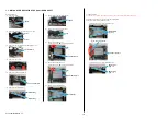
DISASSEMBLY
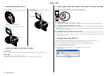
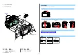
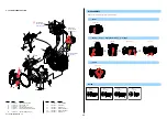
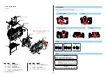
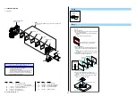
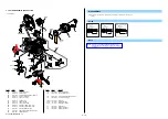
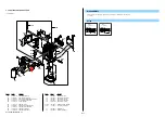
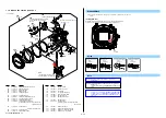
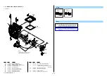
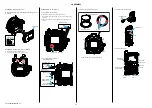
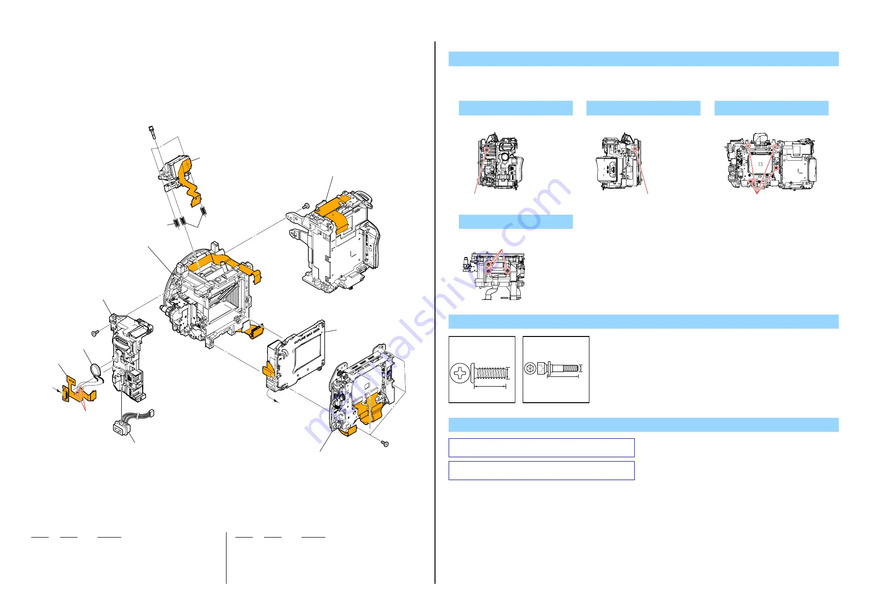
1. Remove in numerical order (
1
to
4
) in the left figure.
2. The meaning of the symbol in left figure is as follows. Be careful when you remove it.
◇
: Solder
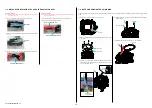
2-1-4. SHUTTER UNIT SECTION
Screw
#12: M1.7 X 5.0 (Tapping)
(Black)
3-080-204-21
1.7
5.0
1
#12 X 1
#12
Right View
3
#12 X 4
#12
Back View
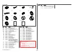
Ref. No.
Part No.
Description
Ref. No.
Part No.
Description
151
1-884-791-22
RM-100 FLEXIBLE BOARD
152
X-2586-484-1 BD JACK HOLDER ASSY (876)
153
1-487-960-23
SHUTTER UNIT (AFE-3032) (Note 1)
154
A-1869-165-A ALX-8631 (Note 2)
(including AF-131 flexible complete board)
155
2-693-420-01 SP,
S
ADJUSTMENT
J901
1-821-194-51
JACK, DC
SP901 1-826-403-61 LOUDSPEAKER
(1.0CM)
#12
3-080-204-21 SCREW,
TAPPING,
P2
#207 4-191-605-01 S
ADJUSTMENT
SCREW
4
#207 X 3
Top View
#207
#207: M1.6 X 8.0
(Silver)
4-191-605-01
8.0
1.6
SP901
J901
#12
#12
#12
A
A
151
1
152
153
(Note 1)
3
Imager Section
2
Battery Holder Section
Mirror Box Section (Sub Unit-1)
#207
4
154
(including AF-131 flexible complete board)
(Note 2)
155
155
2
#12 X 1
#12
Left View
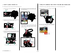
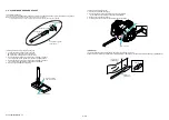
Refer to “Assembly-1: Assemble Shutter Unit” when assem-
bling.
Refer to “Assembly-2: Assemble ALX-8631 (AF Module)”
when assembling.
Note


