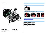
SLT-A58K/A58M/A58Y_L2
2-12
Ref. No.
Part No.
Description
Ref. No.
Part No.
Description
451
A-1935-508-A MB MIRROR BOX SUB UNIT (Note 1, 2)
452
4-141-107-12
MB BODY CAP (Note 2)
453
X-2587-017-1 MB P MOUNT ASSY
455
4-292-534-11
MB RING SP COM
456
4-141-393-01
AP IRIS RING (Note 3)
457
4-292-535-01
AP IDLE GEAR (Note 3)
458
X-2585-653-1 AP TORQUE LIMITER ASSY(T) (Note 3)
459
4-292-530-01
AP OPEN HOLDING SP (Note 3)
460
4-292-529-01
AP SENSOR GEAR (Note 3)
461
A-1849-299-A AP APERTURE UNIT (SERVICE)
(including M902 (aperture motor) and AP-037 flexible
complete board) (Note 3)
462
A-1837-336-A BL CONTACT UNIT
(including BL-038 flexible board)
463
2-689-314-01
ROLLER (B), RING
464
3-268-951-01
SHAFT, RING ROLLER (C)
465
3-277-916-01
ROLLER (C), RING
466
3-283-668-01
ROLLER A (SV), RING
467
4-141-108-01 AF
COUPLER
468
4-292-521-01
AF COUPLER TENSION SP
*
469
2-689-289-11
SHAFT, COUPLER LEVER
*
470
4-141-092-01
MB LENS LOCK PIN
471
4-292-522-01
MB LENS LOCK BUTTON
*
472
4-141-090-01
MB LENS LOCK SP
473
A-1837-337-A AF DRIVING UNIT
(including M901 (AF motor) and AFP-007 flexible
complete board)
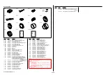
#23
3-080-204-11 SCREW,
TAPPING,
P2
#164
3-268-954-11
SCREW, AF BASE PLATE STOPPER
#165
2-695-434-31
SCREW (T1.7), HEAD PAN TAPPING
#295
2-695-575-21
SCREW (T2), +P1 PAN TAPPNG
Note
Screw
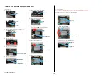
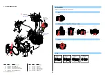
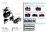
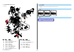
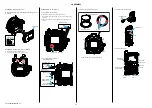
2-1-10. MIRROR BOX SECTION (SUB UNIT-1)
ns: not supplied
#295
#23
#23
#164
ns
ns
#165
#165
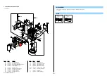
Mirror Box Section (Sub Unit-2)
461
(including M902 (aperture motor) and
AP-037 flexible complete board)
(Note 3)
473
(including M901 (AF motor) and
AFP-007 flexible complete board)
462
(including BL-038 flexible board)
453
455
456
(Note 3)
467
460
(Note 3)
459
(Note 3)
457
(Note 3)
451
(Note 1, 2)
458
(Note 3)
468
465
470
471
472
464
463
466
469
452
(Note 2)
#23: M1.7 X 4.0 (Tapping)
(Black)
3-080-204-11
4.0
1.7
3.9
2.0
#164: M2.0 X 3.9
(Black)
3-268-954-11
3.0
1.7
#165: M1.7 X 3.0 (Tapping)
(Silver)
2-695-434-31
#295: M2.0 X 5.5 (Tapping)
(Silver)
2-695-575-21
5.5
2.0
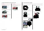
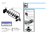
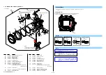
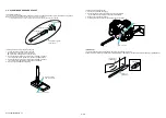
Iris Ring
Iris Ring Removal
Rotate the Iris Ring clockwise, and remove it at the stop position (iris-in end).
At this time, do not rotate the Iris Joint Gear of the AP Aperture Unit.
Refer to “Assembly-3: Mirror Box Sub Unit” when
assembling.
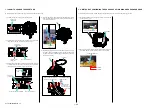
Note 2:
The MB MIRROR BOX SUB UNIT includes a protective
BODY CAP.
This part is supplied only with the MB MIRROR BOX SUB
UNIT.
Note 3:
Refer to “1-9. NOTE ON REMOVING THE AP IRIS RING”
on page 1-5, “1-10. HOW TO CHARGE THE APERTURE”
on page 1-6 and “1-11. METHOD OF CONFIRMING THE
PHASES OF AP IRIS RING AND AP SENSOR GEAR” on
page 1-6.
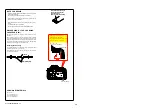
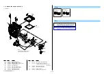
DISASSEMBLY
1. The meaning of the symbol in left figure is as follows. Be careful when you remove it.
◇
: Solder

