6-3
6-1-2 Head Switching Point Adjustment
1) Playback the alignment tape.
2) Intermittently short-circuit the two Test Points on Main PCB while setting the adjustment mode. (See Fig. 6-2)
3) Press the “1, 0” buttons ; remote control adjustment operates automatically. (See Fig. 6-1)
6-1-3 NVRAM Option Setting
1) NVRAM Option is adjusted in the factory.
2) In case Main PCB Micom (IC601) and NVRAM (IC603 ; EEPROM) are replaced, be sure to set the corresponding option number of the
required model. (If the option is not set, the unit will not operate )
1) Intermittently short-circuit the two Test Points on Main PCB. (See Fig. 6-2)
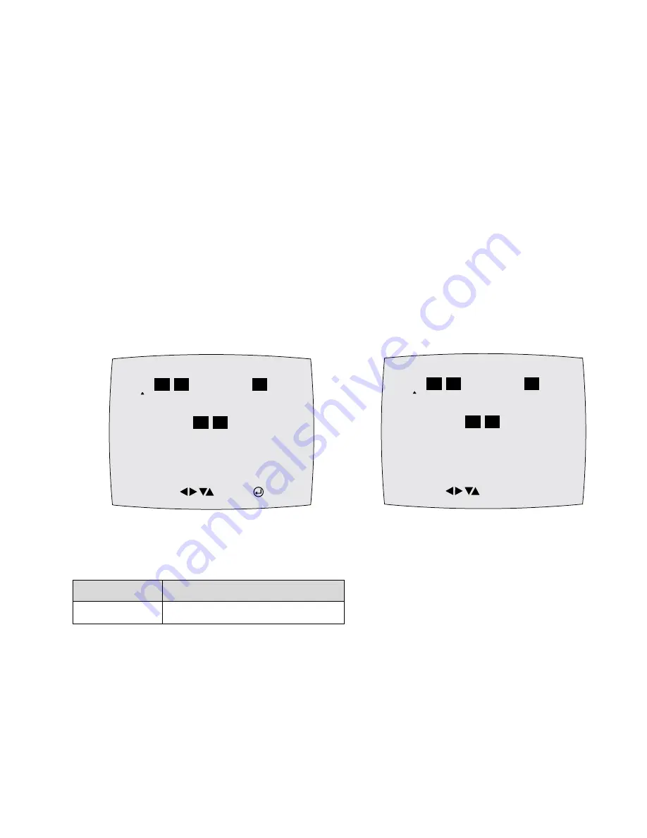
2) Press the “1, 4” buttons on the remote control, then option setting appears. (See Fig. 6-3)
3) Select the option number (See table 6-1) of corresponding model with “
b
,
B
,
v
,
V
” buttons on the remote control.
4) After selecting the option number is completed, press the “
v
” button of remote control.
(If “
v
” button is pressed, the selected number is changescolor. ; See Fig. 6-4)
5) Press the “ENTER” button of remote control again to store the option number.
6) Turn the Power off.
Fig. 6-3
Fig. 6-4
<Table 6-1 NVRAM Option Table>
MOVE : SAVE : ENTER
01
02 03
04
05
06
07
08
09 10 11 12 13 14 15 16
17 18 19
20
21
22 23 24
25 26 27 28 29 30 31 32
33 34 35 36 37 38 39 40
MOVE : COMPLETE
01
02 03
04
05
06
07
08
09 10 11 12 13 14 15 16
17 18 19
20
21
22 23 24
25 26 27 28 29 30 31 32
33 34 35 36 37 38 39 40
MODEL
OPTION NUMBER
SLV-D300P
2, 3, 7, 20, 21
Summary of Contents for SLV-D300P Operating Instructions (SLVD300P)
Page 10: ... 10 MEMO ...
Page 36: ...1 26E MEMO ...
Page 63: ...3 BLOCK DIAGRAM 3 2 3 1 SLV D300P ...
Page 64: ...3 4E MEMO ...
Page 65: ...4 PCB DIAGRAMS 4 1 VCR Main 4 3 4 2 DVD Main 4 7 4 3 Function Timer 4 9 4 2 4 1 SLV D300P ...
Page 66: ...4 3 4 4 4 1 VCR MAIN COMPONENT SIDE ...
Page 67: ...4 6 4 5 CONDUCTOR SIDE ...
Page 68: ...4 7 4 8 COMPONENT SIDE CONDUCTOR SIDE 4 2 DVD MAIN ...
Page 69: ...4 10 4 9 4 3 FUNCTION TIMER COMPONENT SIDE CONDUCTOR SIDE ...
Page 70: ...MEMO 4 12E ...
Page 73: ...5 1 S M P S 5 6 5 5 ...
Page 74: ...5 2 POWER DRIVE 5 7 5 8 ...
Page 75: ...5 3 LOGIC FUNCTION TIMER 5 10 5 9 ...
Page 76: ...5 4 AUDIO VIDEO 5 11 5 12 ...
Page 77: ...5 5 Hi Fi MTS 5 14 5 13 ...
Page 78: ...5 6 INPUT OUTPUT 5 15 5 16 ...
Page 79: ...5 7 DVD MAIN MICON AV DECORDER 5 18 5 17 ...
Page 80: ...5 8 DVD SERVO 5 19 5 20 ...
Page 81: ...5 9 DVD AUDIO VIDEO 5 21 5 22 ...
Page 82: ...MEMO 5 24E ...
Page 96: ...6 14E MEMO ...


