5-2
1-2. SERVICE TOOLS
1-2-1. SERVICE TOOLS
NOTES ON ALIGNMENT TAPES
Select a PAL or NTSC alignment tape from the list below, according to the transmission system of the VCR you are
repairing.
PAL: For models with 625 scanning lines and a field frequency of 50Hz
NTSC: For models with 525 scanning lines and a field frequency of 60Hz
No.
Tool
Tool No.
Remarks
1
Alignment tape NTSC (KRV51N2)
8-192-605-32
NTSC-NORMAL
2
Alignment tape PAL (KRV-51P)
8-192-605-36
PAL-NORMAL
3
Alignment tape NTSC (KRV-52NE)
8-192-605-41
Used to adjust the tape path
4
Alignment tape PAL (KRV-52PL)
8-192-605-46
Used to adjust the tape path
5
Eccentric screw driver
J-6082-044-A
Used to adjust the tape path
6
Nut box
J-6082-045-A
Used to adjust the height of the
lever load assembly
7
Torque dial gauge
H-7099-039-H
Used to measure reel winding
torque
8
Torque dial gauge adaptor
H-7099-035-H
Used to measure reel winding
torque
9
Cassette torque meter(VHJ-063S)
J-6082-011-A
Used to measure back tension
torque
10
Load lever assembly height adjustment tool
J-6090-055-A
Used to adjust the height of the
load lever assembly
11
Torque gauge screwdriver
J-6082-047-A
Used to adjust the tightening torque
of screws
12
3 mm dia. bit for torque screwdriver
J-6082-048-A
Used to replace the bit of the torque
gauge screwdriver
13
Oil
7-661-018-18
14
Grease
7-662-010-04
15
Grease
J-6090-014-A
16
Relay cables
J-6090-057-A
Relay cables of mechanism and
CP-1 PWB assembly
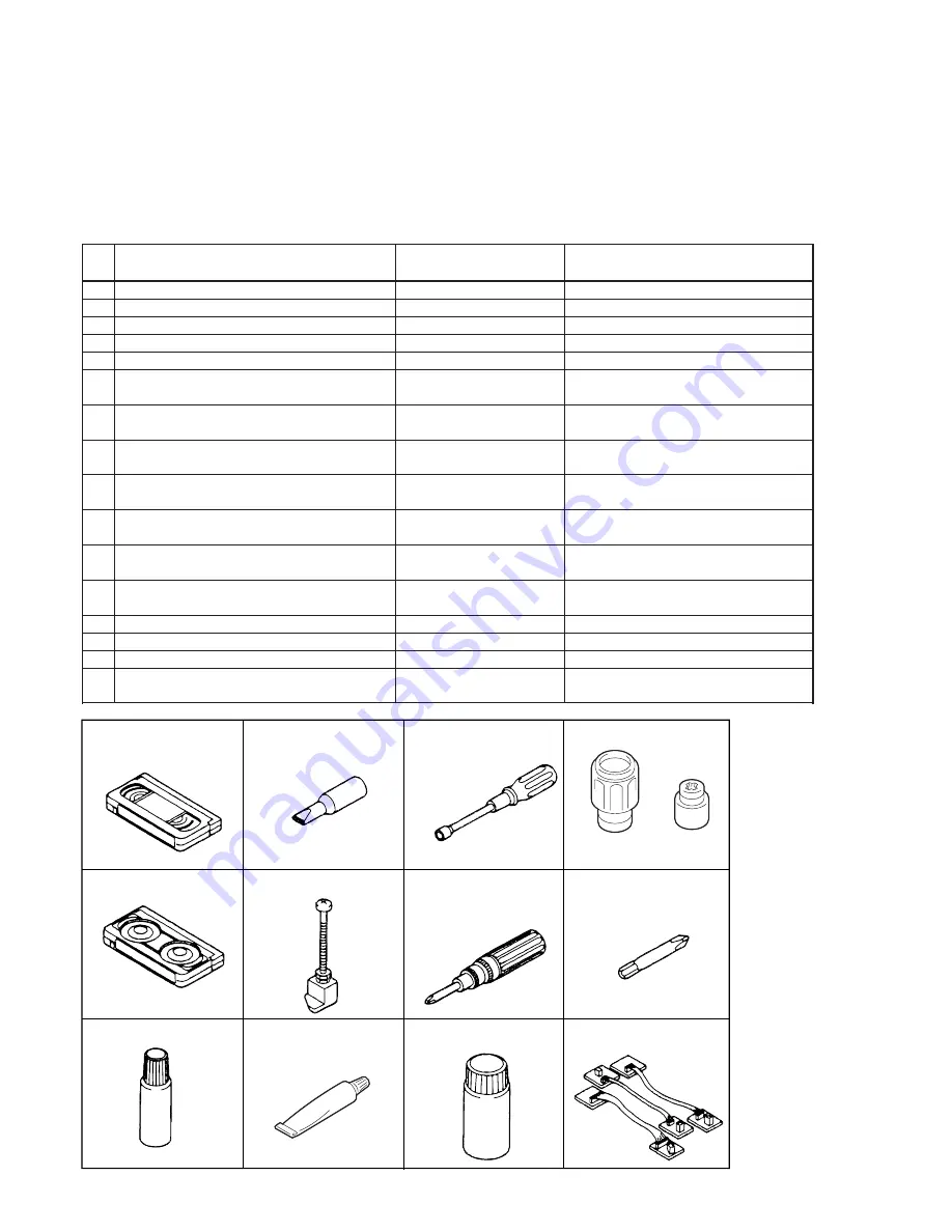
8-192-605-32 (KRV-51N2)
8-192-605-36 (KRV-51P)
8-192-605-41 (KRV-52NE)
8-192-605-46 (KRV-52PL)
J-6082-044-A
J-6090-055-A
J-6082-045-A
J-6082-047-A
J-6090-014-A (EM-L30LG)
J-6082-048-A
J-6082-011-A (VHT-063S)
7-662-010-04 (SGL-505)
No. 1–4
No. 5
No. 6
No. 7, 8
No. 9
No. 10
No. 11
No. 12
No. 13
No. 14
No. 15
No. 16
J-6090-057-A
7-661-018-18 (NT-68)
H-7099-039-H
H-7099-035-H
Fig.1-2-1
Summary of Contents for SLV-L45AR
Page 6: ...1 2 ...
Page 7: ...1 3 ...
Page 8: ...1 4 ...
Page 9: ...1 5 ...
Page 10: ...1 6 ...
Page 11: ...1 7 ...
Page 12: ...1 8 E ...
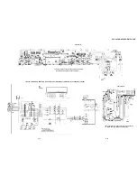
Page 17: ...3 2 MECHANISM CONNECTION DIAGRAM ...
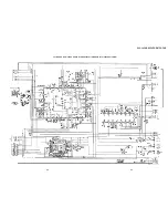
Page 18: ...3 3 3 4 SLV L45AR L65HFAR L75HFAR OVERALL WIRING DIAGRAM SLV L45AR ...
Page 19: ...SLV L45AR L65HFAR L75HFAR OVERALL WIRING DIAGRAM SLV L65HFAR L75HFAR 3 5 3 6 ...
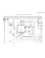
Page 20: ...3 7 3 8 SLV L45AR L65HFAR L75HFAR SYSTEM CONTROL SERVO CIRCUIT DIAGRAM SLV L45AR ...
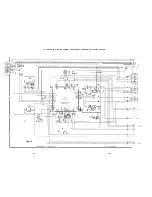
Page 21: ...3 9 3 10 SLV L45AR L65HFAR L75HFAR SYSTEM CONTROL SERVO CIRCUIT DIAGRAM SLV L65HFAR L75HFAR ...
Page 25: ...SLV L45AR L65HFAR L75HFAR 4 3 4 4 CP 1 BOARD VA A VIDEO AUDIO TUNER CIRCUIT DIAGRAM SLV L45AR ...
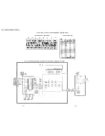
Page 33: ...4 19 4 20 CP 1 BOARD SY A SYSTEM CONTROL SERVO CIRCUIT DIAGRAM SLV L65HFAR L75HFAR ...

