Getting Started
33
Getting Started
3
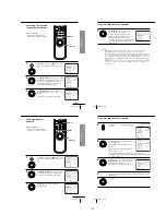
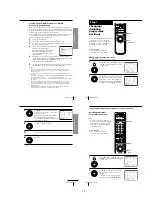
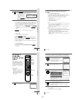
Press CLEAR.
The selected row will be cleared as shown
on the right.
4
Repeat steps 2 and 3 for any other programme positions you want
to disable.
5
Press OK.
SET UP CH AND G-CODE
GUIDE CH
1
2
3
4
5
9
0
56
27
3
SELECT
MOVE PROG
: [
]
: [
]
–
–
–
–
– – – –
– – –
12
16
2
ERASE PROG
: [ CLEAR ]
PROG CH
CLEAR
OK
PLAY
Getting Started
34
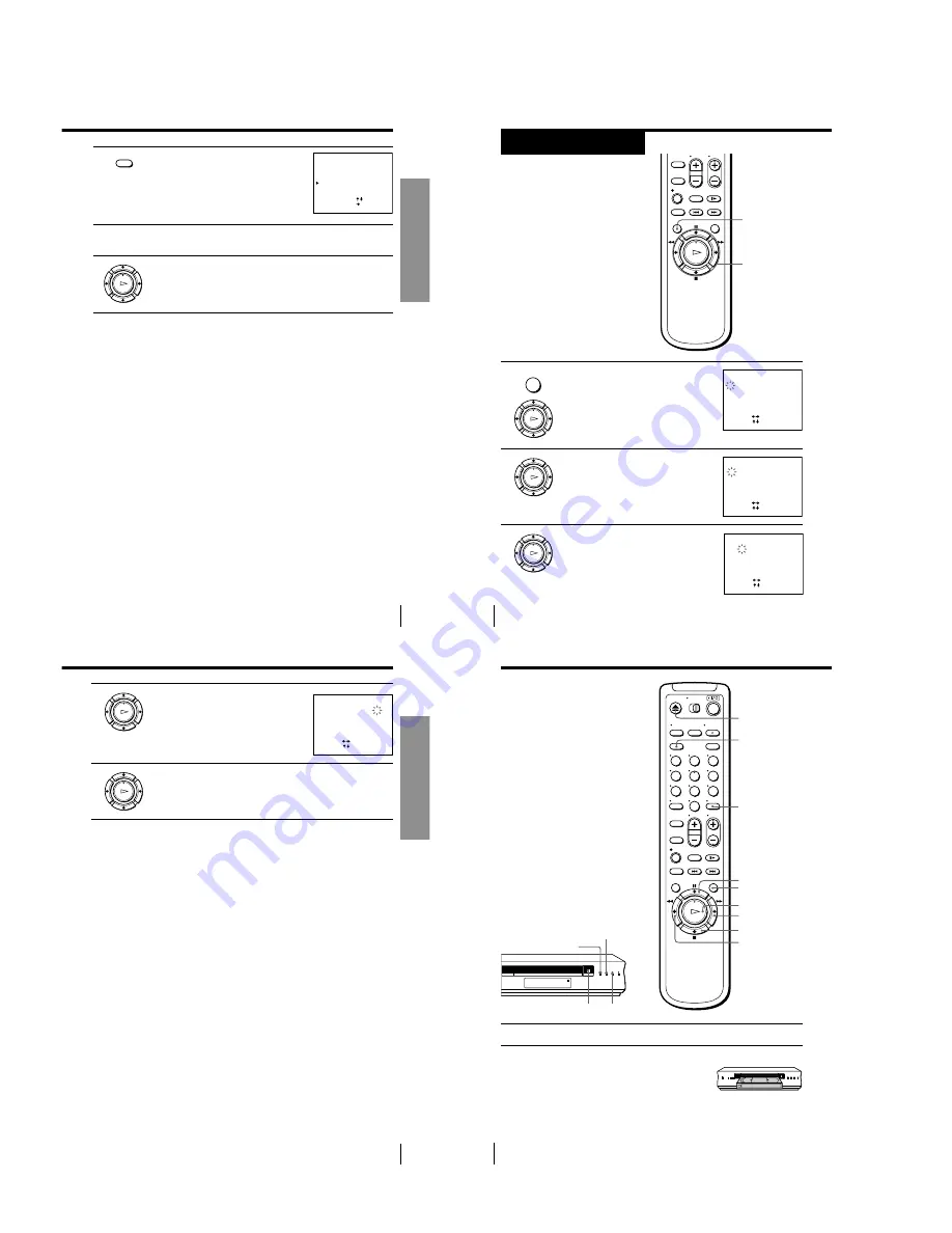
Setting the clock
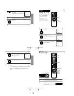
You must set the time and date on the
VCR to be able to use the timer
recording features properly.
Before you start…
• Turn on the VCR and the TV.
• Set the TV to the video channel.
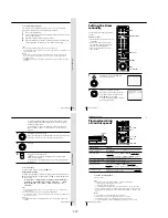
1
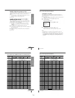
Press MENU, then press
M
/
m
to move the
cursor (
B
) to CLOCK SET and press OK.
2
Press
M
/
m
to set the date.
The day of the week is set automatically.
3
Press
,
to select the month and set the
month using
M
/
m
.
Step 8
CLOCK SET
1 . 1 . 2 0 0 1
MON
0 : 0 0
SELECT
SET
END
: [ OK ]
: [
]
: [
]
CLOCK SET
2
. 1 . 2 0 0 1
THU
0 : 0 0
5
SELECT
SET
END
: [ OK ]
: [
]
: [
]
CLOCK SET
2
. 1
. 2 0 0
0 : 0 0
5
2
1
TUE
SELECT
SET
END
: [ OK ]
: [
]
: [
]
OK
M
/
m
/
<
/
,
MENU
OK
PLAY
MENU
OK
PLAY
OK
PLAY
Getting Started
35
Getting Started
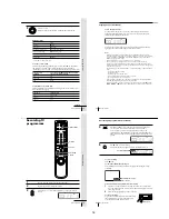
4
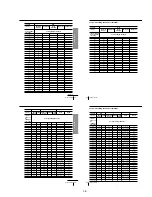
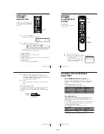
Set the year, hour and minute in sequence,
using
,
to select the item to be set, and
M
/
m
to select the digits.
5
Press OK to start the clock.
Tip
• To change the digits when setting, press
<
to return to the item to be changed, and
select the digits using
M
/
m
.
Note
• The menu disappears automatically if you do not proceed for more than a few
minutes.
CLOCK SET
2
. 1
. 2 0 0 1 TUE
5
2
5 : 3 0
1
SELECT
SET
END
: [ OK ]
: [
]
: [
]
OK
PLAY
OK
PLAY
Basic Operations
36
Basic Operations
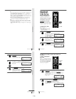
Playing a tape
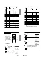
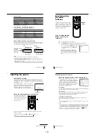
1
Turn on your TV and set it to the video channel.
2
Insert a tape.
The VCR turns on and starts playing
automatically if you insert a tape with its
safety tab removed.
DISPLAY
H
PLAY
M
FF
x
STOP
m
REW
X
PAUSE
CLEAR
EJECT
1
2
3
4
5
6
7
8
9
0
s
(stop)
H
(play)
j
(rewind)
A
(eject)
COLOR SYSTEM
1-8
Summary of Contents for SLV-LF1
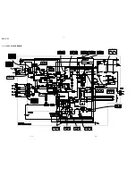
Page 26: ...SLV LF1 3 1 3 2 SECTION 3 BLOCK DIAGRAMS 3 1 OVERALL BLOCK DIAGRAM ...
Page 29: ...SLV LF1 3 4 AUDIO BLOCK DIAGRAM 3 7 3 8 ...
Page 30: ...SLV LF1 3 5 TUNER BLOCK DIAGRAM 3 9 3 10 ...
Page 31: ...SLV LF1 3 6 MODE CONTROL BLOCK DIAGRAM 3 11 3 12 ...


