Basic Operations
37
Basic Operations
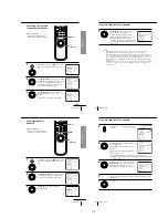
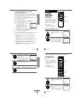
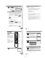
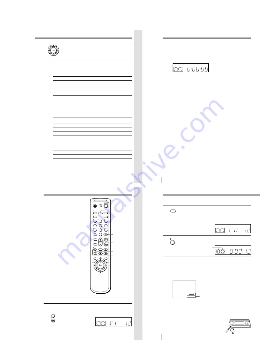
To
Stop play
Pause play
Resume play after pause
Fast-forward the tape
Rewind the tape
Eject the tape
* On the remote commander only
To set the colour system
If streaks appear during playback, press COLOR SYSTEM on the remote
commander to conform to the system that the tape was recorded in.
(Normally, the colour system is correctly set whenever the tape is inserted.)
If your tape was
recorded in
PAL
MESECAM
NTSC
If your TV is
PAL
NTSC 4.43
NTSC 3.58
Press COLOR SYSTEM until the indication below
appears in the display window.
PAL
PAL
NTSC
Press
x
STOP
X
PAUSE*
X
PAUSE* or
H
PLAY
M
FF* during stop
m
REW during stop
Z
EJECT
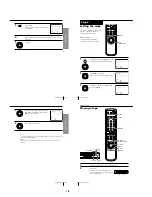
To play an NTSC-recorded tape
Set NTSC PB in the SET UP MENU according to the colour system of your
TV. For details, see page 61.
Set NTSC PB to
ON PAL TV
4.43
3.58
3
Press
H
PLAY.
When the tape reaches the end, it will rewind automatically.
continued
OK
PLAY
Additional tasks
Basic Operations
38
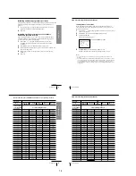
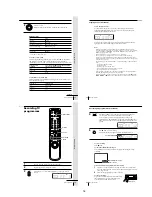
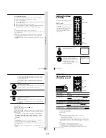
To use the time counter
At the point on the tape that you want to find later, press CLEAR. The
counter in the display window resets to “0:00:00.” Search for the point
afterwards by referring to the counter.
To display the counter on the TV screen, press DISPLAY. Press DISPLAY
again and the counter will disappear from the TV screen.
Notes
• When you play back a tape recorded in the PAL or MESECAM colour system,
streaks may appear even if the colour system setting is set to AUTO. If so, select the
colour system PAL or MESECAM in the PAL/MESECAM option of the SET UP
MENU (see page 61 for details).
• The counter resets to “0:00:00” whenever a tape is reinserted.
• The counter stops counting when it comes to a portion with no recording.
• If a tape has portions recorded in both PAL and NTSC systems, the time counter
reading will not be correct. This is due to the difference between the counting cycles
of the two colour systems.
• Depending on your TV, the following may occur while playing an NTSC-recorded
tape:
– the picture is black and white
– the picture shakes
– no picture appears on the TV screen
– black streaks appear horizontally on the TV screen
– the colour density increases or decreases.
• Tapes recorded in the LP mode of other NTSC system VCRs can be played back on
this VCR, but the picture quality cannot be guaranteed.
• While setting the menu on the TV screen, you cannot use the
H
PLAY,
X
PAUSE,
M
FF,
m
REW or
x
STOP buttons. These buttons are used for menu operations.
Playing a tape (continued)
SP
APC
Basic Operations
39
Basic Operations
Recording TV
programmes
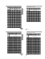
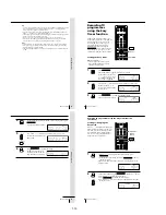
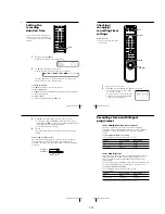
1
Turn on your TV and set it to the video channel.
2
Insert a tape with its safety tab in place.
3
Press PROG +/– to select the programme position you want to
record.
REC SPEED
z
REC
INPUT SELECT
DISPLAY
1
2
3
4
5
6
7
8
9
0
SP
APC
PROG
PROG +/–
continued
Basic Operations
40
Recording TV programmes (continued)
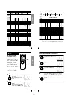
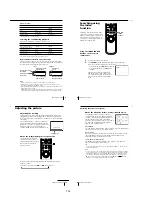
4
Press REC SPEED to select the tape speed (SP or LP for the PAL
colour system, and SP or EP for the NTSC colour system).
LP (Long Play) provides recording time twice as long as SP
(Standard Play). EP (Extended Play) provides recording time three
times as long as SP. However, SP produces better picture and audio
quality.
5
Press
z
REC to start recording.
The recording indicator lights up red in the display window.
To stop recording
Press
x
STOP.
To check the remaining tape length
Press DISPLAY. The white bar indicates the approximate length of tape
remaining.
Remaining tape length
Time counter
To watch another TV programme while recording
1
If the TV is connected to the VCR using an audio/video cable, set the
TV to TV input. If the TV is connected to the VCR using only the aerial
cable, skip this step.
2
Select another programme position on the TV.
To save a recording
To prevent accidental erasure, break off the safety
tab as illustrated. To record on the tape again,
cover the tab hole with adhesive tape.
Safety tab
REC SPEED
REC
LP
APC
S
E
:
: 2
2
–
0 0
0
Recording indicator
LP
APC
1-9
Summary of Contents for SLV-LF1
Page 26: ...SLV LF1 3 1 3 2 SECTION 3 BLOCK DIAGRAMS 3 1 OVERALL BLOCK DIAGRAM ...
Page 29: ...SLV LF1 3 4 AUDIO BLOCK DIAGRAM 3 7 3 8 ...
Page 30: ...SLV LF1 3 5 TUNER BLOCK DIAGRAM 3 9 3 10 ...
Page 31: ...SLV LF1 3 6 MODE CONTROL BLOCK DIAGRAM 3 11 3 12 ...


