1-2
8
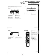
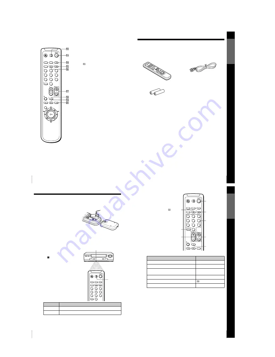
Index to parts and controls
L
[TV]
/
[VIDEO]
remote control switch
(10)
M
?
/
1
(on/standby) switch (11) (33)
N
INPUT SELECT button (30) (37)
(47)
O
t
TV/VIDEO button (11) (13) (30)
P
DISPLAY button (30)
Q
PROG (programme) +/– buttons (11)
(29)
R
WIDE button (for TV) (11)
S
y
SLOW button (39)
T
×2 button (39)
1
2
3
4
5
6
7
8
9
0
G
e
tting Star
te
d
9
Unpacking
Step 1 : Unpacking
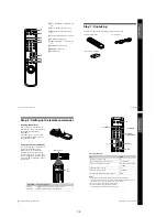
Check that you have received the following items with the VCR:
• Remote commander
• Aerial cable
• R6 (size AA) batteries
G
e
tting Star
te
d
11
Setting up the remote commander
TV control buttons
Notes
• With normal use, the batteries should last about three to six months.
• If you do not use the remote commander for an extended period of time, remove
the batteries to avoid possible damage from battery leakage.
• Do not use a new battery together with an old one.
• Do not use different types of batteries together.
• Some buttons may not work with certain Sony TVs.
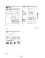
To
Press
Set the TV to standby mode
?
/
1
Select an input source: aerial in or line in
t
TV/VIDEO
Select the TV’s programme position
Programme number buttons,
-
, PROG +/–
Adjust the volume of the TV
2
+/–
Call up the on-screen display
DISPLAY
Switch to/from wide mode of a Sony wide TV.
WIDE
1
2
3
4
5
6
7
8
9
0
Programme
number buttons
WIDE
DISPLAY
PROG +/–
?
/
1
t
TV/VIDEO
2
+/–
-
10
Setting up the remote commander
Step 2 : Setting up the remote commander
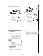
Inserting the batteries
Insert two R6 (size AA) batteries by
matching the + and – on the batteries to
the diagram inside the battery
compartment.
Insert the negative (–) end first, then
push in and down until the positive (+)
end clicks into position.
Using the remote commander
You can use this remote commander to
operate this VCR and a Sony TV.
Buttons on the remote commander
marked with a dot (
•
) can be used to
operate your Sony TV. If the TV does
not have the
symbol near the remote
sensor, this remote commander will not
operate the TV.
To operate
Set
[TV]
/
[VIDEO]
to
the VCR
[VIDEO]
and point at the remote sensor at the VCR
a Sony TV
[TV]
and point at the remote sensor at the TV
1
2
3
4
5
6
7
8
9
0
Remote sensor
[TV]
/
[VIDEO]
Summary of Contents for SLV-SE210B
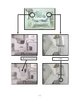
Page 7: ... 7 BRACKET HANDLING Twist ...
Page 8: ... 8 MEMO ...
Page 25: ...SLV SE210B SE210D SE210G SX110A SX110B CONDUCTOR SIDE 3 3 3 4E ...
Page 27: ...SLV SE210B SE210D SE210G SX110A SX110B 4 1 S M P S Π4 3 4 4 ...
Page 28: ...SLV SE210B SE210D SE210G SX110A SX110B 4 2 Power 4 5 4 6 ...
Page 29: ...SLV SE210B SE210D SE210G SX110A SX110B 4 3 System Control Servo ˇ ˆ 4 7 4 8 ...
Page 30: ...SLV SE210B SE210D SE210G SX110A SX110B Æ Ú Ò Ô ı 4 4 Audio Video 4 9 4 10 ...
Page 31: ...SLV SE210B SE210D SE210G SX110A SX110B 4 5 TM Block 4 11 4 12 ...
Page 32: ...SLV SE210B SE210D SE210G SX110A SX110B 4 6 OSD VPS PDC 4 13 4 14 ...
Page 33: ...SLV SE210B SE210D SE210G SX110A SX110B 4 7 SECAM SLV SE210B SX110B model 4 15 4 16 ...
Page 34: ...SLV SE210B SE210D SE210G SX110A SX110B 4 8 Input Output 2 Scart Jack 4 17 4 18 ...
Page 35: ...SLV SE210B SE210D SE210G SX110A SX110B 4 9 Input Output 1 Scart Jack 4 19 4 20 ...
Page 37: ...SLV SE210B SE210D SE210G SX110A SX110B 4 23 4 24E ...


