


98
Chapter 3: Sonoma Mixer
C
hap
te
r 3:
So
no
m
a
Mi
xer
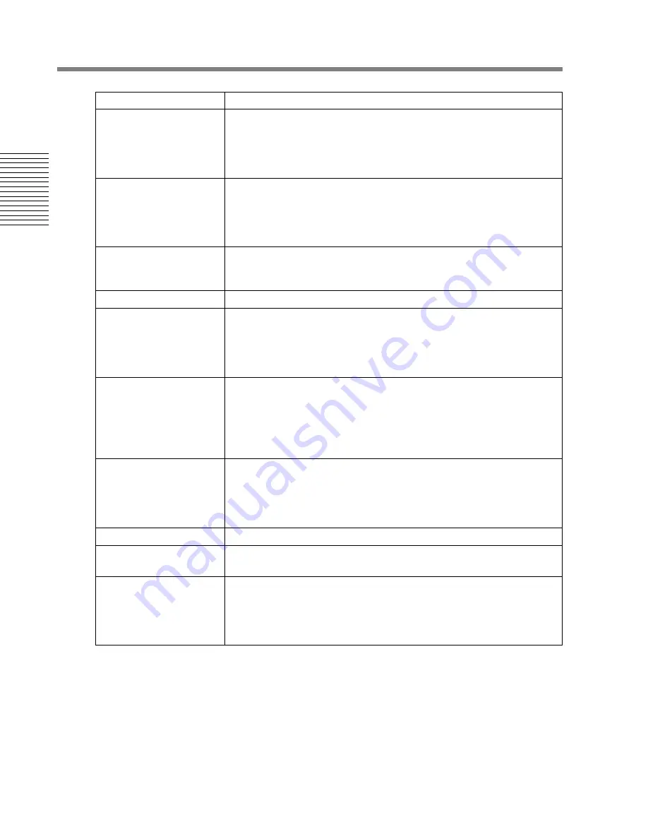
Dynamics
Limiter “CL1” & Compressor/Limiter “CL2”
Stereo: permanently linked
Surround: all channels except LFE permanently linked, with a switch that
unlinks and switches out the LFE channel only for both CL1 and CL2
sections.
Annex E Filter
LPF on all output channels
Different settings for surround and stereo modes
In/out switch
Frequency: [20 kHz
→
85 kHz], Normalized 20kHz
Slope: [0 dB/oct
→
–36 dB/oct], Normalized 0 dB/oct
Master Fader
Stereo or Surround program mode
Fader gain: [–1024 dB
→
+10 dB], Normalized 0 dB
Cut button
Master meter pre/post
Switches input meter between pre- and post-input gain
Monitor Assign
The following modes are available:
PROGRAM
RECORD RETURN
AUX SEND
SHORT CHANNEL INPUT [CH 9-16]
Meter Assign
The following modes are available:
PROGRAM
RECORD RETURN
AUX SEND
SHORT CHANNEL INPUT [CH 9-16]
FOLLOW MONITOR
Monitor Section
Dim* and Cut* switches
Dimmer gain control [–40 dB
→
0 dB], Normalized –20 dB
Monitor gain control* [–1024 dB
→
+10 dB], Normalized 0 dB
Loudspeaker gain trims in Setup window (see later)
Stereo Loudspeaker Output Enable switch
Master Cuts/Solos
6 cut buttons, 6 solo buttons
Fold-down
Surround to Stereo follows ITU-R BS.775-1 Annex 3 recommendations
Stereo to Mono is {0.707L + 0.707R}
Aux Master
4 sets of controls, 1 for each of AUX send 1+2, 3+4, 5+6 and 7+8.
Each control comprising:
• Cut button
• Gain control [-1024 dB
→
+10 dB]
1 Overall Cut button
*. Indicates a control which can also be accessed elsewhere.
Table 3-6
Mixer Master Controls
Item
Specifications


