– 11 –
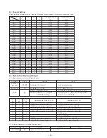
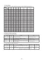
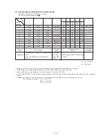
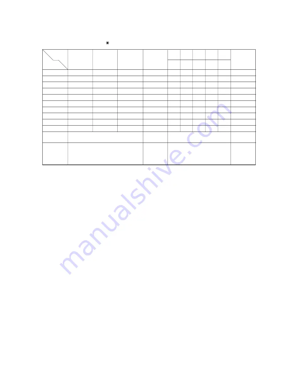
2-3. Key processing (Setting the manual test mode)
1
(Upper position) (Lower Position) Set with #.
2
3X# can be substituted with X
.
• By pressing the CH key there is increment of the channel. However, this does not include the test channel.
• Control of the power source during 38# DATA TX is (TX&RX RF&RX AF=ON) in 44# state.
• Control of the power source during the 70# key check mode is 41# state (TX OFF).
• For CH setting, SIGOUT control and power source control (with the exception of above-mentioned 38# state) the state can be set indepen-
dently.
Example : In 15 ch, the order for carrying out TX modulation level and RSSI (H) sensitivity setting is as follows :
The following are possible : 15#
n
44#
n
36#
36#
n
15#
n
44#
44#
n
36#
n
15#
Upper
4
position
0
1
2
3
7
Lower
TX
RX
RX
MIC
Lk
position
RF
AF
0
QUIT
10ch
20ch
Batt Alarm
H
A
L
T
G
KEY TEST
1
1ch
11ch
21ch
CHARG DET
G
g
G
G
G
2
2ch
12ch
22ch
G
g
g
G
G
3
3ch
13ch
23ch
g
g
G
G
G
4
4ch
14ch
24ch
RX LOCK
g
g
g
G
G
5
5ch
15ch
25ch
TX LOCK
g
g
g
g
G
6
6ch
16ch
T1ch
RSSI (H)
g
g
g
g
g
7
7ch
17ch
T2ch
RSSI (L)
–
–
–
–
–
8
8ch
18ch
T3ch
DATA TX
–
–
–
–
–
9
9ch
19ch
T4ch
–
–
–
–
–
Purpose
CH setting only
SIGOUT
Only power source
General
control
control
operation
The standard is external line communication Condition
Application
state.
suveillance
Measurement mode of consumption
State for stsndard electrical adjustment
with TALK
current.
process.
LED.
g
: ON,
G
: OFF
Lk : KEY LED


