— 61 —
1
2
3
4
5
6
7
8
9
10 - 13
14
15
16
17
18
19
20
21
22
23
24
25
26
27
28
29
30
31
32
33
34
35
36
37
38
39
40
41
42 - 48
49 - 52
53 - 56
57, 58
59 - 72
73
74 - 76
77
78 - 80
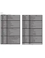
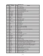
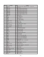
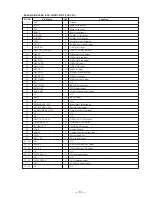
I/O
Function
Pin Name
• BASE MAIN BOARD IC201 TMP87CM21F (TAD CPU)
Pin No.
VSS
XOUT
XIN
RESET
TADACK
TADREQ
TEST
STOP
ASICREQ
ASIC DATA BUS0-3
DSP SC
DSP SDI
DSP SDO
DSP ACKN
ASIC ACK
DSP CSN
DSP PDN
DSP RSTN
DSP HRNW
NC
OFF HOOK
RING DET
PARA DET
NC
BEEP
NC
RINGER SEL. SW
BIT RATE SEL. SW
ANS.MODE SEL. SW
NC
NC
NEW CALL LED
ANSWER LED
IN-USE LED
VASS
VAREF
VDD
EEC CTL.
NC
ROW0-3
COL0-3
NC
LCD SEG13-0
NC
LCD COM2-0
VLC
NC
–
O
I
I
O
O
I
I
I
I/O
O
I
O
I
I
O
O
O
O
–
O
I
I
–
O
–
I
I
I
–
–
O
O
O
–
I
–
I
–
O
I
–
O
–
O
–
–
Ground
Main clock output
Main clock input
Reset signal input
TADuC ACK output
TADuC REQ output
Test pin for out-going test
TADuC power down input
ASIC REQ input
ASIC
↔
TADuC data bus
DSP serial clock output
DSP serial data input
DSP serial data output
DSP ACK input
ASIC ACK input
DSP CS output
DSP power down output
DSP reset output
DSP read/write output
N.C.
RELAY drive output
RING detect input
PARA off-hook detect input
N.C.
BEEP output
N.C.
Ringer time select input
Bit rate select input
Answer mode select input
N.C.
N.C.
NEW CALL LED control
ANSWER LED control
IN-USE LED control
Analog Ground
Analog reference voltage input
Power 5v)
EEC control input
N.C.
4*4Key Matrix ROW output
4*4Key Matrix COL input
N.C.
LCD segment output
N.C.
LCD common output
LCD drive power supply
N.C.

