– 6 –
SECTION 2
DISASSEMBLY
Note :
Follow the disassembly procedure in the numerical order given.
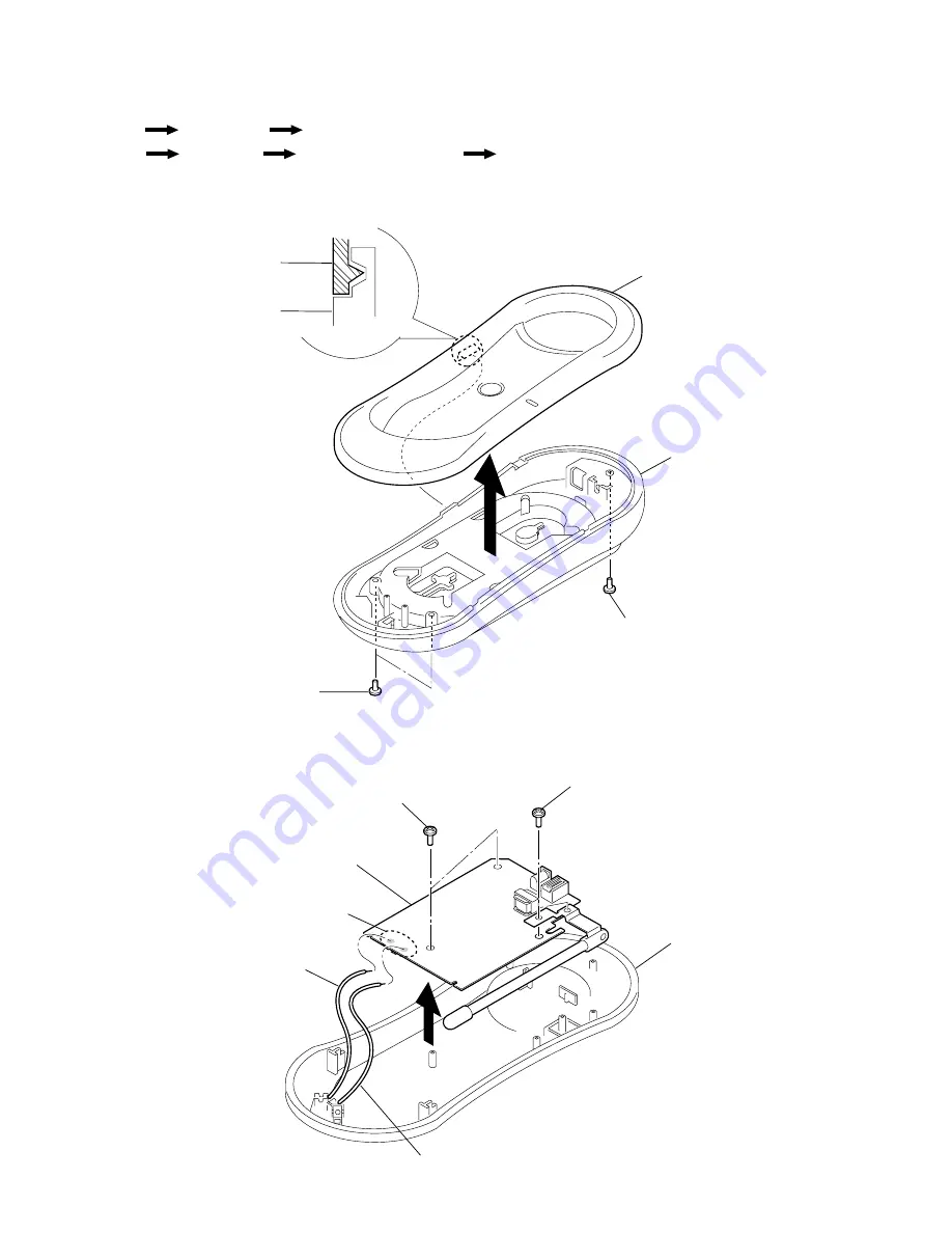
2-1. CABINET (UPPER)
2-2. BASE MAIN BOARD
r
The equipment can be removed using the following procedure.
Cabinet (upper)
Base unit
Base main board
Cabinet (rear)
Handset
Jack board (SPP-N1003 only)
Hand main board
2
Claw
1
Screw (+P 3x8)
1
Screws (+P 3x8)
Cabinet (lower)
Cabinet (lower)
Cabinet (upper)
Cabinet (upper)
3
2
Screws (+BTP 2.6x8)
1
Screws (+BTP 2.6x8)
Cabinet (lower)
4
White
Red
3
Remove solder
Base main board
Summary of Contents for SPP-N1001
Page 3: ... 3 SECTION 1 GENERAL This section is extracted from instruction manual ...
Page 4: ... 4 ...
Page 5: ... 5 SPP N1003 ...
Page 48: ...15 SPP N1001 N1003 ...


