13
3-1.
ACCESS METHOD
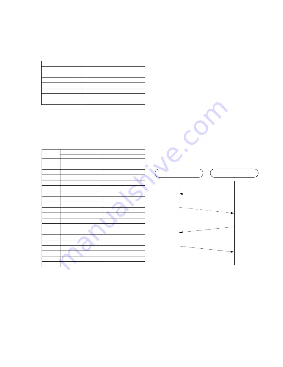
1. Transfer Format & Rate
The transfer format & rate of our system is as follows;
Table 3-1. Transfer method
Access method
FDMA-TDD
Channel number
14 channel
Channel spacing
1.2 MHz
Modulation method
DBPSK
Baseband transfer rate
960 Kbps
Spread method
Direct Sequence Spread Spectrum
Chip rate
12 chips/bit
Data transfer rate
80 Kbps
2. Channel Number & Frequencies
RF channels occupy the frequency band 902 – 928 MHz are num-
bered 1 to 14.
RF channel numbers & center frequencies are specified as fol-
lows.
Table 3-2. Channel number & Channel frequency
Channel
Channel Center Frequency (MHz)
Number
UNIT CH PLAN
TEST MODE CH PLAN
1
907.2
904.2
2
908.4
904.8
3
909.6
906.0
4
910.8
907.2
5
912.0
908.4
6
913.2
909.6
7
914.4
910.8
8
915.6
912.0
9
916.8
913.2
10
918.0
914.4
11
919.2
915.6
12
920.4
916.8
13
921.6
918.0
14
922.8
919.2
15
920.4
16
921.6
17
922.8
18
924.0
19
925.2
20
925.8
SECTION 3
900 MHz SYSTEM OPERATION
3-2.
PROTOCOL
1. General
This system realizes the TX/RX superframe by TDD system. The
relation of master/slave dose not decide identification regarding
the protocol between BASE UNIT and HANDSET, but the initi-
ated side is the master and the requested side is the slave when the
RF link has been established.
2. Initial Acquisition
In order to establish the RF link between BASE UNIT and HAND-
SET, both of BASE UNIT and HANDSET need to have the same
system ID. When “power” is applied to this system, the system
have to do Initial Acquisition in order to have the same system ID.
It is to exchange a parameter when the HANDSET is parked on
the BASE UNIT, as soon as the system do System Parameters Re-
initialization.
3. System Parameter Re-initialization
This System Parameters Re-initialization can realize that the
HANDSET is parked on the BASE UNIT. So after the BASE UNIT
recognized to be parked the HANDSET, the BASE UNIT calcu-
lates a system parameter, and then it outputs this data from the
ARTO port, and then the system establishes the RF link. In order
to establish this link, the HANDSET send the A-Frame to the BASE
UNIT after the HANDSET received the system parameter, and
then the BASE UNIT send the A-Frame to the HANDSET. The
process of System Parameters Re-initialization is as follows.
Fig. 3-1. System Parameters Re-initialization
BASE UNIT
HANDSET
System ID
confirmed
System ID
confirmed
(Park Detect)
(Park Detect)
(PARK)
System Parameters
A-Frame
A-Frame
*
Note)
The UNIT has 14 channels according to the UNIT CH
PLAN while the number of channels which can be used in
the test mode are those in the TEST MODE CH PLAN.


