background image

6

Summary of Contents for SPP-S9101 - Cordless Telephone

Page 1: ...1 MICROFILM SPP S9101 US Model Canadian Model SPECIFICATIONS SERVICE MANUAL CORDLESS TELEPHONE ...

Page 2: ...6 7 IC Pin Functions 32 7 EXPLODED VIEWS 7 1 Handset Section 35 7 2 Base Unit Section 36 8 ELECTRICAL PARTS LIST 37 Notes on chip component replacement Never reuse a disconnected chip component Notice that the minus side of a tantalum capacitor may be damaged by heat SAFETY RELATED COMPONENT WARNING COMPONENTS IDENTIFIED BY MARK OR DOTTED LINE WITH MARK ON THE SCHEMATIC DIAGRAMS AND IN THE PARTS L...

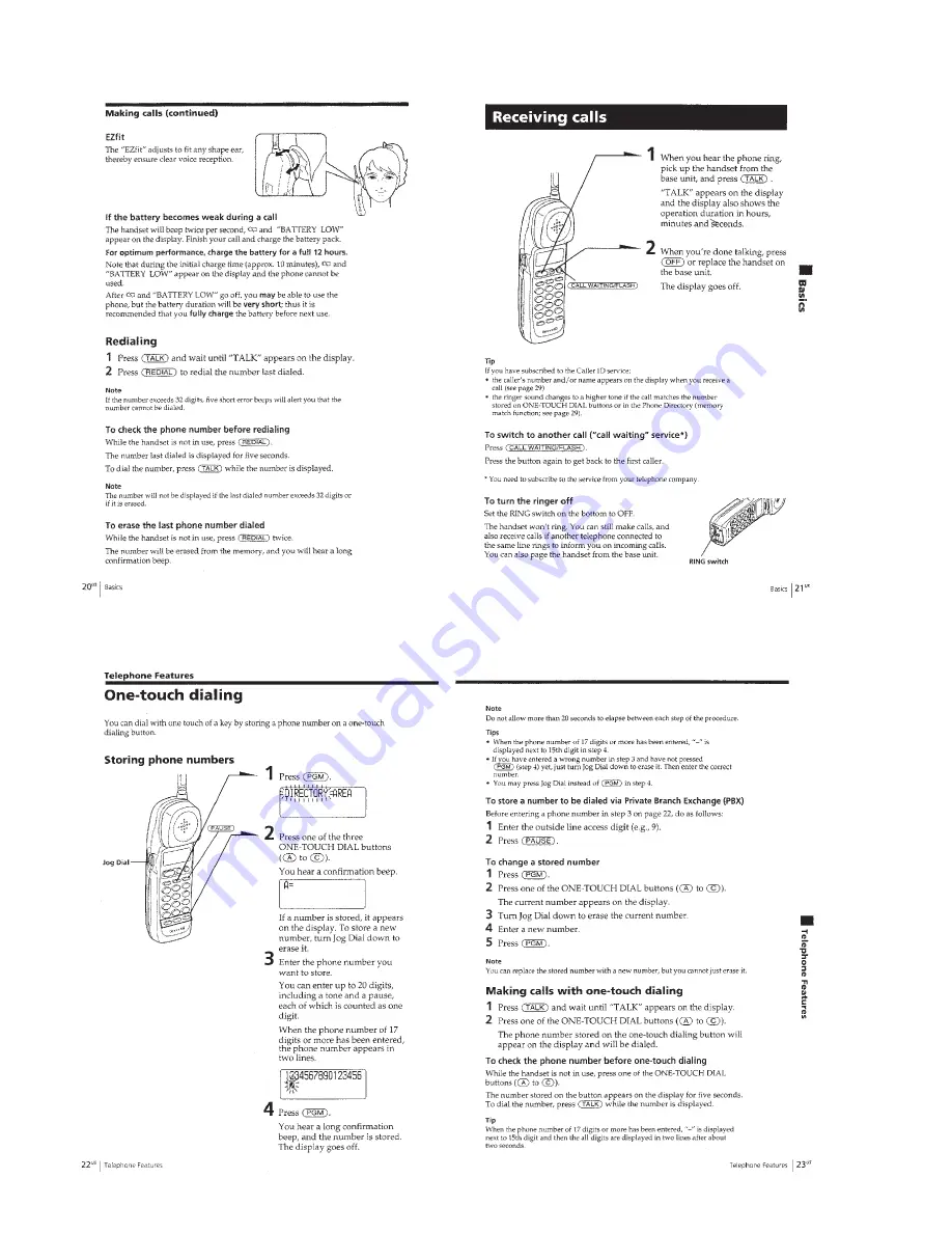
Page 3: ...3 SECTION 1 GENERAL This section is extracted from instruction manual ...

Page 4: ...4 ...

Page 5: ...5 ...

Page 6: ...6 ...

Page 7: ...7 ...

Page 8: ...8 ...

Page 9: ...9 ...

Page 10: ...10 ...

Page 11: ...11 ...

Page 12: ...BTP 2 6x8 Screw BTP 2 6x12 Hand main board Helical antenna Connector CN601 1 2 3 4 5 2 2 CABINET REAR HANDSET 2 3 HAND MAIN BOARD HANDSET 2 1 BATTERY CASE LID HANDSET 2 4 CABINET AND BOARDS BASE UNIT 1 Two screws P3x10 7 Four screws P3x10 8 Base Main board 0 LED board Button H L Lens Basic 5 Cabinet Upper 3 Cabinet Lower assy 2 Two screws P3x10 9 Two screws BTP2 6x8 6 Antenna terminal 4 Three conn...

Page 13: ...quested side is the slave when the RF link has been established 2 Initial Acquisition In order to establish the RF link between BASE UNIT and HAND SET both of BASE UNIT and HANDSET need to have the same system ID When power is applied to this system the system have to do Initial Acquisition in order to have the same system ID It is to exchange a parameter when the HANDSET is parked on the BASE UNI...

Page 14: ...f the BASE UNIT can not receive the A Frame of Heart beat from the HANDSET it become link error and the system become error recovery mode 4 Stand by Mode Operation 1 HANDSET When the HANDSET is the stand by mode sleep mode the HANDSET do the intermittent operation for power save be cause the HANDSET is the battery operation This process of stand by mode operation is as follows 10 sec 10 sec Heart ...

Page 15: ...ent are as fol lows Fig 3 3 Link Establishment protocol Master TX Master RX Slave RX Slave TX Master Time Slot Trip Delay TX RX TX RX TX A V A V V V V A V A V Fig 3 4 Link Establishment Timing Chart 6 State Change Tarmination After the RF link between HANDSET and BASE UNIT was es tablished a movement of each state State ON Hook OFF Hook PAGE InterCom etc is sent through supervisory bits 7 Error Re...

Page 16: ...one in this order Ring Detect Test 1 Rings the Normal Ringer synchronized with an external call com ing in and blinks the IC501 Pin New Call LED MES SAGE LED at the same time CID Type 1 Reception Test 1 When an external call comes in receive the CID Type 1 signal the CID signal timing conforms to the regular specifications If it could be received correctly determined by whether the checksum is cor...

Page 17: ...r 1ch continuous transmission mode middle power 1ch continuous transmission mode low power 10ch continuous transmission mode high power 10ch continuous transmission mode middle power 10ch continuous transmission mode low power 20ch continuous transmission mode high power 20ch continuous transmission mode middle power 20ch continuous transmission mode low power 1ch continuous reception mode 10ch co...

Page 18: ...to return to test mode first and then set the desired mode A Test Resetting Command 0 0 0 1 Mode Operation Ends the test mode Clears the EEPROM data Sounds the ACK beep if OK Exits the test mode and returns to the normal operating state Returns to test mode idling Note In the continuous reception test the All 1 s Data in ASIC should be used Command Mode Operation 1ch continuous reception LNA AGC O...

Page 19: ...t to seventh side band from Center Frequency Transmission Frequency f0 CH1 is under 10 dB Refer Fig 1 and Fig 2 If output wave form deteriorates side band appears like Fig 3 and Fig 4 4 4 RF TESTING This test is for checking the RF system without disassembling the set in servicing Perform measurement using the spectrum analyzer and jig antenna 4 4 1 RF Testing method Please follow the below instru...

Page 20: ...tting Test mode Continuous Transmit mode CH1 High Power Refer to Test Mode on page 16 Measurement Measure transmitting wave f0 Formula of center frequency Refer Fig 5 Specification 904 2 MHz 27 kHz Center Frequency Fig 4 Fig 5 Confirm Transmitting output Measuring process Setting Spectrum analyzer Center frequency 904 2 MHz CH1 RBW 1 MHz VBW 100 kHz Span 5 MHz Setting Test mode Continuous Transmit...

Page 21: ...BASE UNIT MIN 18 dBm at High power Include location loss Measurement Measure peak level by Spectrum analyzer CENTER 903 600 MHz RES BW 1 0 MHz SPAN 5 000 MHz SWP 20 0 msec 903 587 MHz MKR 3 67 dBm AT 10 dB 0 dBm REF PEAK LOG WA SB SC FC CORR PLOTTER ADRS 10 dB VBW 100 kHz 0 ...

Page 22: ...see page 13 2 Checking TX Center Frequency Setting short TP515 TP567 GND level meter oscilloscope TP558 RXIP TP557 RXIN TP556 RXQP TP555 RXQN TP567 GND SSG ANTENNA TERMINAL frequency counter ANTENNA TERMINAL Procedure 1 Short TP515 GND and TP567 GND on the BASE MAIN board in the base unit 2 Place the base unit in the Continuous Transmit more CH1 High power 3 Measure the ANT OUT frequency of the RF...

Page 23: ...ng short TP820 TP814 GND level meter oscilloscope TP804 RXIP TP803 RXIN TP802 RXQP TP801 RXQN TP814 GND SSG ANTENNA TERMINAL frequency counter ANTENNA TERMINAL peak power meter ANTENNA TERMINAL TP812 Procedure 1 Short TP555 GND and TP814 GND on the HAND MAIN board in the handset 2 Place the handset in the Continuous Transmit more CH1 High power 3 Measure the ANT OUT frequency of the RF module in t...

Page 24: ...X Output TP555 RXQN TP556 RXQP TP557 RXIN TP558 RXIP level meter Chcking RX I Q Output Level short TP515 TP567 GND Checking TX Center Frequency short TP820 TP814 GND Checking TX Center Frequency ANTENNA TERMINAL SSG Checking RX I Q Output Level frequency counter Checking TX Center Frequency peak power meter Checking TX Output TP801 RXQN TP802 RXQP TP803 RXIN TP804 RXIP level meter Chcking RX I Q O...

Page 25: ... SECTION IC501 5 OSCI 4 Vp p 9 6 MHz 1 HANDSET SECTION IC401 5 OSCI 4 Vp p 9 6 MHz Note The components identi fied by mark or dotted line with mark are criti cal for safety Replace only with part number specified Note Les composants identifiés par une marque sont critiques pour la sécurité Ne les remplacer que par une piéce portant le numéro spécifié 6 1 IC BLOCK DIAGRAMS BASE MAIN Board IC502 S 2...

Page 26: ...ion D323 G 6 D326 D 1 D327 C 2 IC501 F 6 IC901 A 3 Q902 D 4 Q903 D 4 Q904 E 3 Q905 E 2 Q907 F 2 Q908 G 1 6 2 PRINTED WIRING BOARDS BASE UNIT LED SECTION Semiconductor Location Ref No Location D571 A 7 D572 A 6 D573 A 5 D574 A 4 Q571 A 7 Q572 A 6 Page 27 ...

Page 27: ...A 5 D108 A 6 D301 D 2 D303 E 10 D304 E 9 D305 C 9 D306 D 2 D309 C 8 D310 E 9 D321 F 6 D322 F 5 D324 G 5 D325 F 7 D502 F 5 D503 E 2 D901 B 7 D921 B 7 D922 B 7 D923 A 7 D924 A 7 IC301 D 2 IC302 D 5 IC502 G 8 IC902 D 4 Q101 A 6 Q102 D 4 Q103 D 3 Q301 D 8 Q302 G 10 Q303 G 9 Q304 E 10 Q305 E 9 Q306 G 9 Q307 C 9 Page 26 ...

Page 28: ...am See page 26 27 for Printed Wiring Board See page 32 for IC Pin Functions 13 14 Page 29 Page 29 A SPARE BATTERY LED SPARE BATTERY LED TO SPARE BATTERY TERMINAL FOR_SPARE_BATTERY SPARE BATTERY LED MESSAGE LED SPARE BATTERY LED MESSAGE LED 15 16 11 12 17 JC505 0 JC508 0 JC501 0 JC502 0 JC509 0 SPARE BATTERY B JC504 0 ...

Page 29: ...E3 Page 28 A MESSAGE LED SPARE BATTERY MESSAGE Page 28 JC510 0 JC511 0 JC905 0 JC903 0 17 13 14 16 15 VREF OUT VDD VSS SIGNAL IN XTAL OUT XTAL IN ENABLE IN DETECT OUT 5 DETECT ENABLE JC904 0 C967 0 001 B C966 0 1p F TP583 C315 0 1p B R320 330k R321 220k IC903 CMX673P1 STTVTER TONE IC903 18 SPARE BATTERY LED 0 0 0 5 1 2 8 ...

Page 30: ...D209 C 11 D401 A 4 D410 B 7 D413 A 5 D414 B 7 D415 A 7 D422 A 4 D601 B 13 D801 A 2 IC201 C 10 IC401 B 4 IC402 B 6 IC403 B 7 Q201 D 9 Q202 C 10 Q203 C 10 Q204 C 11 Q405 B 11 Q601 B 13 Semiconductor Location Ref No Location D404 C 11 D405 B 11 D406 C 9 D407 B 9 D408 C 4 D409 B 4 D411 B 2 D412 B 2 D416 A 4 D417 B 4 D418 B 4 D419 B 4 D421 B 4 D423 B 3 Q402 B 6 Q404 B 2 ...

Page 31: ... S9101 31 31 6 6 SCHEMATIC DIAGRAM HANDSET SECTION See page 25 for Waveforms See page 33 for IC Pin Functions QUAD EXCLUSIVE OR GATE Q404 B SWITCH LIQUID CRYSTAL DISPLAY UNIT ILLUMINATION L204 22nH LCD401 ...

Page 32: ... 0 1mF capacitor Analog power supply Line driver output DAC channel Analog 0V power supply Positive speaker driver output DAC channel Negative speaker driver output DAC channel Not used open Digital 0V power supply Digital power supply 2 7 5 5 Volts Analog 0V power supply Pin No Pin Name I O Function 51 52 53 54 55 56 57 58 59 60 61 62 63 64 65 66 67 68 69 70 71 72 73 74 75 76 77 78 79 80 81 82 83...

Page 33: ... used open HAND BASE select input VDD supply to pad ring VSS supply to pad ring Not used open Not used open VDD supply to core VSS supply to core Not used open Clock signal output to the EEPROM Two way data bus with the EEPROM ART input Park input active low on base station active high on handset ART output Frame sync Serial data input Serial data output Main clock input Not used open Analog 0V po...

Page 34: ...ctional control LCD data Keypad bidirectional control LCD data Keypad bidirectional control LCD data Keypad bidirectional control LCD data Not used open VSS supply to core VDD supply to core Not used open VSS supply to pad ring VDD supply to pad ring LNA select Receive enable Synthesizer data 9 6 MHz clock used by synthesizer Synthesizer clock Synthesizer strobe Synthesizer power VDD supply to A D...

Page 35: ...816 01 LID HAND BATTERY CASE 17 3 033 764 01 CUSHION MIC 18 3 034 821 01 HOLDER LCD 19 3 039 836 01 SHEET LCD 20 3 039 837 01 SHEET H S REAR 21 3 034 817 01 PANEL LED 22 3 038 844 01 MICROPHONE CUSHION ANT1 1 754 081 11 ANTENNA HELICAL LCD401 1 418 604 11 LCD UNIT SP1 1 505 695 11 SPEAKER 2 1CM 1 3 034 812 01 PAD EAR 2 3 014 329 01 CUSHION SP 3 X 3377 753 1 HINGEASSY 4 3 034 810 01 SPRING LEAF 5 3...

Page 36: ...SE 65 3 034 835 01 PANEL C ID 66 3 037 079 01 BODY ANTENNA ANT701 3 038 540 01 TERMINAL ANTENNA 51 3 034 827 01 CABINET UPPER 52 A 3622 341 A BASE MAIN BOARD COMPLETE 53 3 034 830 01 HOLDER HAND SET 54 3 034 832 01 LENS C ID 55 3 034 831 01 BUTTON H L 56 1 674 890 11 LED BOARD 57 3 034 833 01 TERMINAL BASE CHARGE 58 X 3377 755 1 CABINET LOWER ASSY 59 3 037 081 01 PLUG ANTENNA not supplied ANT701 1...

Page 37: ...AMIC CHIP 0 001uF 10 50V C329 1 164 489 11 CERAMIC CHIP 0 22uF 10 16V C501 1 163 038 00 CERAMIC CHIP 0 1uF 25V C502 1 163 038 00 CERAMIC CHIP 0 1uF 25V C503 1 163 235 11 CERAMIC CHIP 22PF 5 50V C504 1 163 038 00 CERAMIC CHIP 0 1uF 25V C505 1 163 038 00 CERAMIC CHIP 0 1uF 25V C506 1 163 038 00 CERAMIC CHIP 0 1uF 25V C507 1 126 964 11 ELECT 10uF 20 50V C508 1 163 031 11 CERAMIC CHIP 0 01uF 50V C509 ...

Page 38: ... D325 8 719 037 02 DIODE RD6 8SB T1 D326 8 719 158 55 DIODE RD15SB T1 D327 8 719 158 55 DIODE RD15SB T1 D502 8 719 914 44 DIODE DAP202K T 146 D503 8 719 914 44 DIODE DAP202K T 146 D901 8 719 991 33 DIODE 1SS133T 77 D921 8 719 991 33 DIODE 1SS133T 77 D922 8 719 991 33 DIODE 1SS133T 77 D923 8 719 991 33 DIODE 1SS133T 7 D924 8 719 991 33 DIODE 1SS133T 77 FUSE F101 1 533 542 11 FUSE 250V 500mA IC IC30...

Page 39: ... 10W R508 1 216 097 00 RES CHIP 100K 5 1 10W R509 1 216 073 00 METAL CHIP 10K 5 1 10W R511 1 216 041 00 METAL CHIP 470 5 1 10W R512 1 216 009 00 RES CHIP 22 5 1 10W R513 1 216 864 11 METAL CHIP 0 5 1 16W R514 1 216 864 11 METAL CHIP 0 5 1 16W R515 1 216 817 11 METAL CHIP 470 5 1 16W R516 1 216 057 00 METAL CHIP 2 2K 5 1 10W R517 1 216 121 00 RES CHIP 1M 5 1 10W R518 1 216 809 11 METAL CHIP 100 5 1...

Page 40: ...MIC CHIP 0 01uF 50V C204 1 163 235 11 CERAMIC CHIP 22PF 5 50V C205 1 163 031 11 CERAMIC CHIP 0 01uF 50V C206 1 164 005 11 CERAMIC CHIP 0 47uF 25V C207 1 163 033 00 CERAMIC CHIP 0 022uF 50V C208 1 163 251 11 CERAMIC CHIP 100PF 5 50V C209 1 163 033 00 CERAMIC CHIP 0 022uF 50V C210 1 163 033 00 CERAMIC CHIP 0 022uF 50V C211 1 163 038 00 CERAMIC CHIP 0 1uF 25V C212 1 163 125 00 CAP CERAMIC CHIP 220PF ...

Page 41: ...80730AN DT T1 IC401 8 759 597 21 IC R6797 71 IC402 8 759 392 92 IC AT24C32N 10SI 1 8 TR IC403 8 759 523 96 IC TC74VHC86FT EL COIL L201 1 412 945 11 INDUCTOR 3 3uH L202 1 216 296 00 SHORT 0 L203 1 216 296 00 SHORT 0 L204 1 410 379 21 INDUCTOR CHIP 6 8uH L205 1 410 379 21 INDUCTOR CHIP 6 8uH L206 1 410 379 21 INDUCTOR CHIP 6 8uH L207 1 410 379 21 INDUCTOR CHIP 6 8uH L401 1 216 823 11 METAL CHIP 1 5K...

Page 42: ... 5 1 10W R602 1 216 065 00 METAL CHIP 4 7K 5 1 10W R603 1 216 033 00 METAL CHIP 220 5 1 10W R605 1 216 045 00 METAL CHIP 680 5 1 10W R606 1 216 037 00 METAL CHIP 330 5 1 10W R607 1 216 009 00 RES CHIP 22 5 1 10W R618 1 216 017 00 RES CHIP 47 5 1 10W R619 1 216 017 00 RES CHIP 47 5 1 10W R620 1 216 057 00 METAL CHIP 2 2K 5 1 10W R621 1 216 017 00 RES CHIP 47 5 1 10W R622 1 216 017 00 RES CHIP 47 5 ...

Page 43: ...66 976 11 GUIDE QUICK START US ENGLISH SPANISH 3 866 976 21 GUIDE QUICK START CND ENGLISH FRENCH 3 936 680 01 LABEL ADDRESS HARDWARE LIST 1 7 685 134 19 SCREW BTP 2 6X8 TYPE2 N S 2 7 685 136 19 SCREW BTP 2 6X12 TYPE2 N S 3 7 685 647 79 SCREW P 3X10 TYPE2 NON SLIT 4 7 685 133 19 SCREW BTP 2 6X6 TYPE2 N S Les composants identifiés par une marque sont critiques pour la sécurité Ne les remplacer que p...

Page 44: ...44 Sony Corporation Digital Telecommunication Company 99H090216 1 Printed in Japan 1999 8 Published by Mobile Electronics Company Quality Assurance Dept 9 926 599 11 SPP S9101 ...

Reviews: